Relay configuration for an electro-pneumatic train

a technology of electro-pneumatic trains and relay configuration, which is applied in the direction of braking systems, braking components, transportation and packaging, etc., can solve the problems of increasing the cost of installing an electro-pneumatic control device on each railroad car, and the use of electro-pneumatic-pneumatic valves in freight trains is very limited, so as to reduce the number of electro-pneumatic brake control valves

Active Publication Date: 2006-06-29
NEW YORK AIR BRAKE CORP
View PDF12 Cites 10 Cited by
  • Summary
  • Abstract
  • Description
  • Claims
  • Application Information

AI Technical Summary

Benefits of technology

[0009] This reduces the number of electropneumatic brake control valves. The improved brake control valve includes a relay valve mounted at an interface of the manifold.

Problems solved by technology

Thus, the use of electropneumatic-pneumatic valves in the freight trains has been very limited.
Although the technology for electropneumatic brake control valves has been implemented and accepted, there is still a cost factor in installing an electropneumatic-controlled device on each railroad car.

Method used


Image

  • Relay configuration for an electro-pneumatic train
  • Relay configuration for an electro-pneumatic train
  • Relay configuration for an electro-pneumatic train

Examples


Embodiment Construction

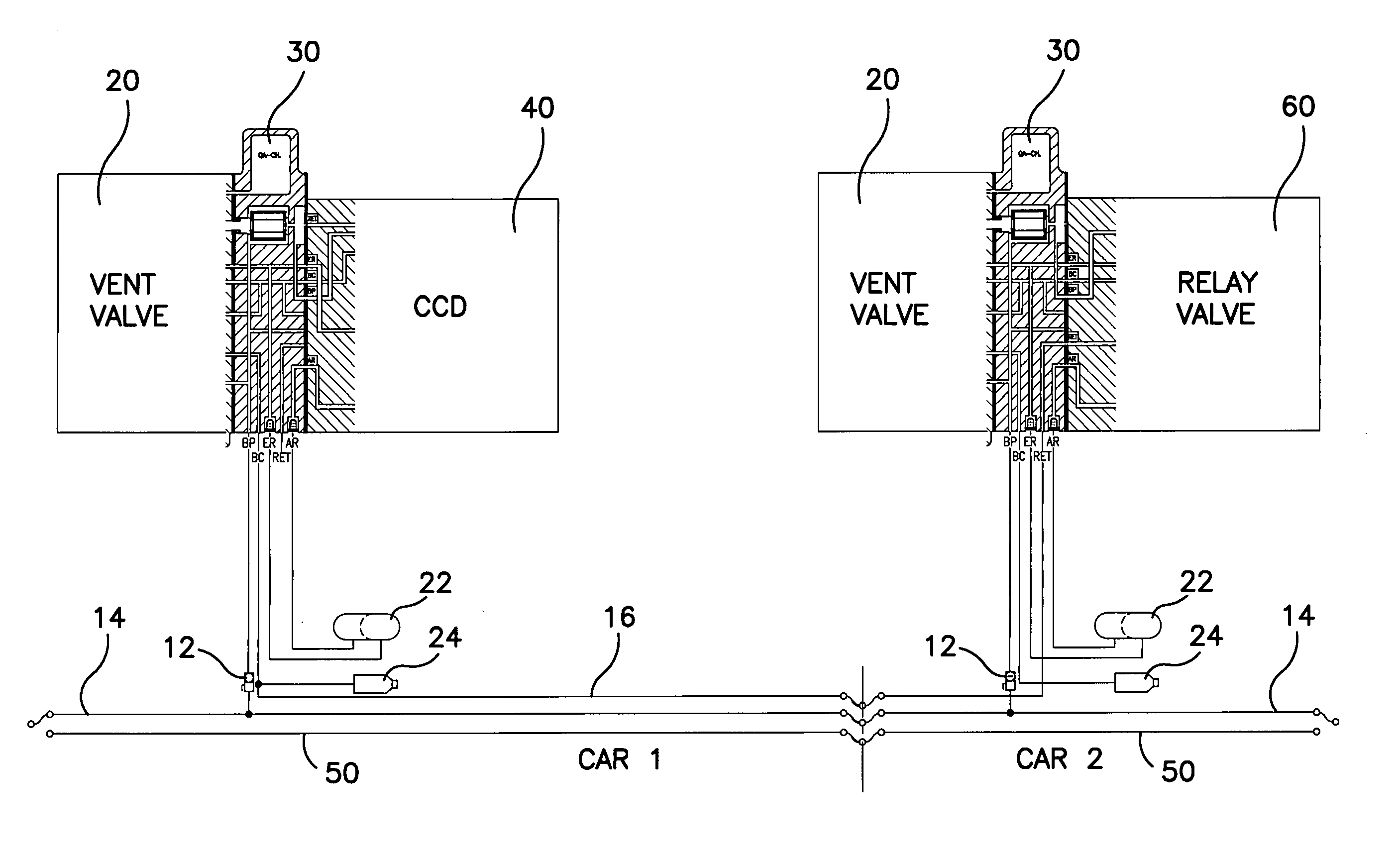
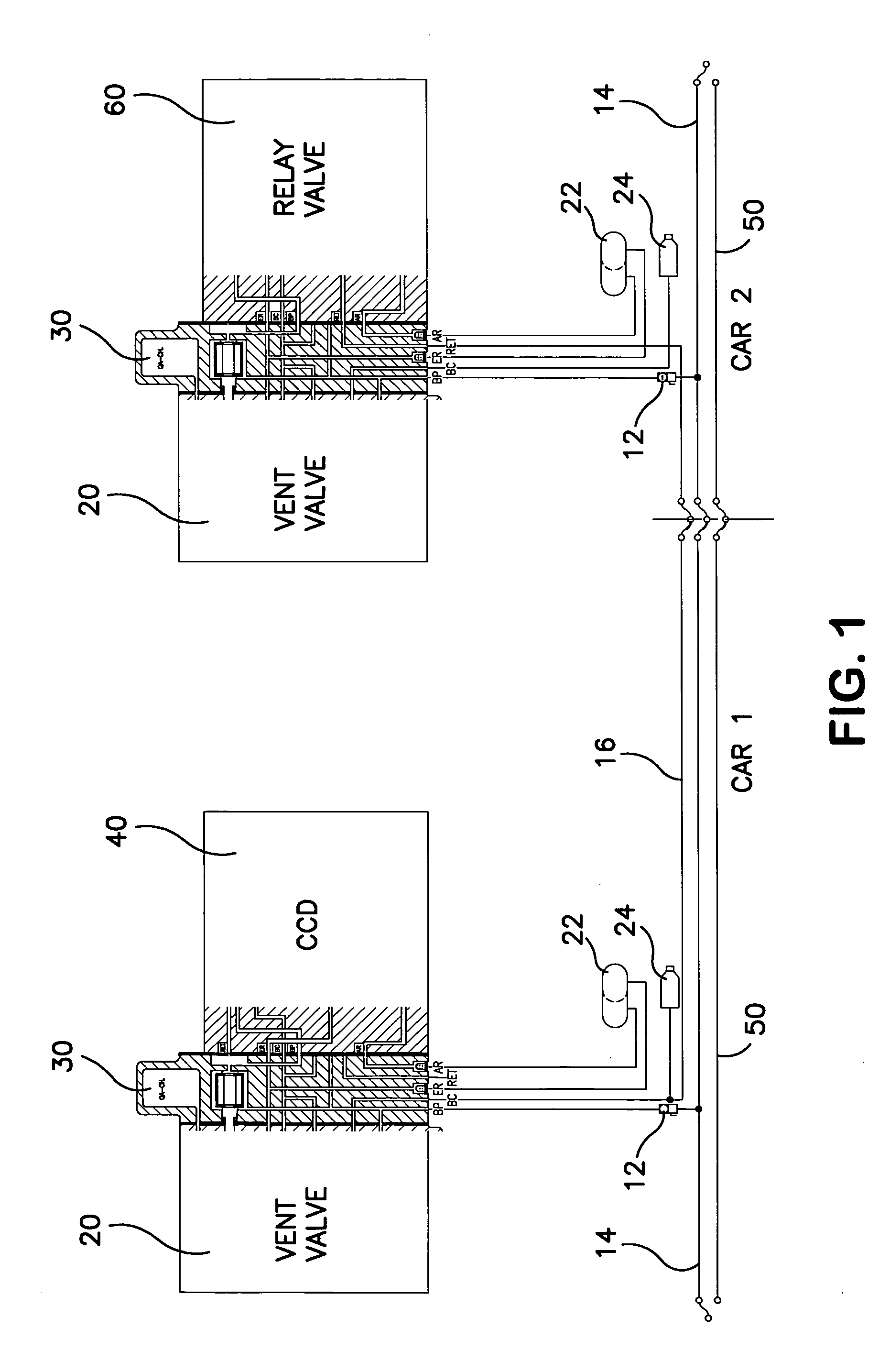
[0019] As shown in FIG. 1, two cars are interconnected by a brake pipe 14 and an electrical train line 50, which carries power and communication signals to the various electropneumatic brake control valves. An additional pipe 16 connects the first and second cars. As will be described below, pipe 16 is either a new pipe or an existing pipe within the train. Various trains have a holding brake pipe, which is not used in the present electropneumatic brake control systems and, therefore, is available. Each of the cars includes a standard manifold 30 connected via cut-off valve 12 to the brake pipe 14. A pair of reservoirs 22 are also connected to the manifold 30, as is the brake cylinder 24. The standard inlet ports of the manifold 30 are brake pipe BP, brake cylinder BC, emergency reservoir ER, auxiliary reservoir AR and an exhaust / retainer port RET.

[0020] On car 1, an electropneumatic brake control valve 40 is mounted on the service interface for the pipe bracket 30. These devices a...


PUM


Abstract

A relay valve configuration which can be used with various cars in an electropneumatic train and under the control of one of the electropneumatic brake control valves. The improved brake control valve includes a relay valve mounted at an interface of the manifold. The valve has a source inlet connected to the reservoir interface port, an inlet connected to atmosphere, an outlet connected to the brake cylinder interface port and a control inlet connected to the exhaust interface port. The valve is responsive to the control inlet connected to the exhaust interface port to selectively connect the brake cylinder interface port either to the reservoir interface port or atmosphere. The exhaust interface port in AAR is known as the retainer port. A check valve/choke is also mounted on the manifold of the interface and is in the same housing as the relay valve.

Description

BACKGROUND AND SUMMARY OF THE DISCLOSURE [0001] The present invention relates generally to electropneumatic (“EP”) brake control valves and, more specifically, to a relay valve for use in an electropneumatic train. [0002] Electropneumatic brake control valves are well known in the passenger railroad art and the mass transit railroad art. Because the trains are short and are not involved generally in a mix and match at an interchange of different equipment, the ability to provide pneumatic and electrical control throughout the train has been readily available in the passenger and the mass transit systems. In freight trains, the trains may involve as much as 100 cars stretching over one mile or more. The individual cars may lay idle in harsh environments for up to a year without use. Also, because of the long distance they travel, the cars are continuously moved from one consist to another as it travels to its destination. [0003] Thus, the use of electropneumatic-pneumatic valves in t...

Claims


Application Information

Patent Timeline
Patent Type & Authority Applications(United States)
IPC IPC(8): B60T13/74
CPCB60T13/683B60T15/021
Inventor MCLAUGHLIN, BRYANTRUGLIO, JAMES R.WRIGHT, ERIC
Owner NEW YORK AIR BRAKE CORP
Why Eureka
Try Eureka