Wireless probe system and method for a fueling environment

a probe system and fueling environment technology, applied in the field of leak detection systems, to achieve the effect of reducing the risk of interferen

Active Publication Date: 2006-06-29
VEEDER ROOT
View PDF35 Cites 9 Cited by
  • Summary
  • Abstract
  • Description
  • Claims
  • Application Information

AI Technical Summary

Benefits of technology

[0010] Several variations on the present invention exist. In an alternate embodiment, the site communicator never sends an acknowledgment signal, and the repeater always sends the transmitted sensor data (along with the appended repeater identification) to the site communicator transceiver. In another alternate embodiment, the repeater delays a random amount of time to transmit the transmitted sensor data (along with the appended repeater identification) to the site communicator transceiver. The randomness of the time delay may help minimize the risk of interference from other signals from other repeaters. The sensor and the sensor transceiver may be powered by batteries, or may draw power from nearby components such as the fuel dispenser. Likewise, the repeater may have a battery power source or may draw power from a nearby component such as the fuel dispenser. The housing for the sensor transceiver should ideally be leak resistant, and may optionally be intrinsically safe. The protocol between the various components may also be varied. For example, in an alternate embodiment, if the site communicator transceiver sends out an acknowledgement signal before the repeater sends its copy of the transmitted sensor data, the repeater may not send the duplicate copy to the site communicator transceiver.

Problems solved by technology

However, recognizing that circumstances may not be ideal, the repeater is also positioned such that it receives the transmitted sensor data A predetermined amount of time after the repeater receives the transmitted sensor data, the repeater appends a repeater identification to the transmitted sensor data, and transmits the transmitted sensor data (along with the appended repeater identification) to the site communicator transceiver.

Method used


Image

  • Wireless probe system and method for a fueling environment
  • Wireless probe system and method for a fueling environment
  • Wireless probe system and method for a fueling environment

Examples


Embodiment Construction

[0024] The embodiments set forth below represent the necessary information to enable those skilled in the art to practice the invention and illustrate the best mode of practicing the invention. Upon reading the following description in light of the accompanying drawing figures, those skilled in the art will understand the concepts of the invention and will recognize applications of these concepts not particularly addressed herein. It should be understood that these concepts and applications fall within the scope of the disclosure and the accompanying claims.

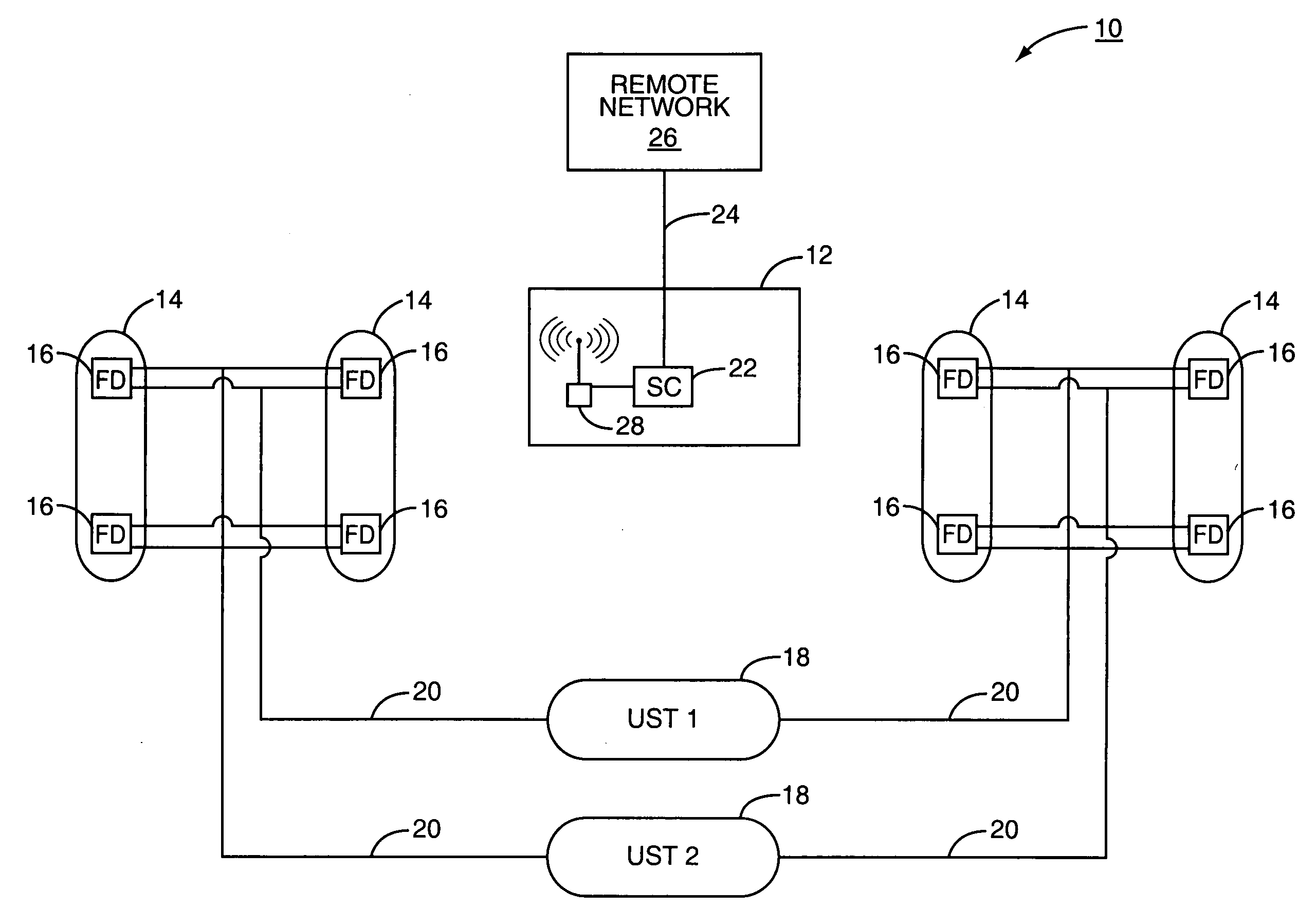
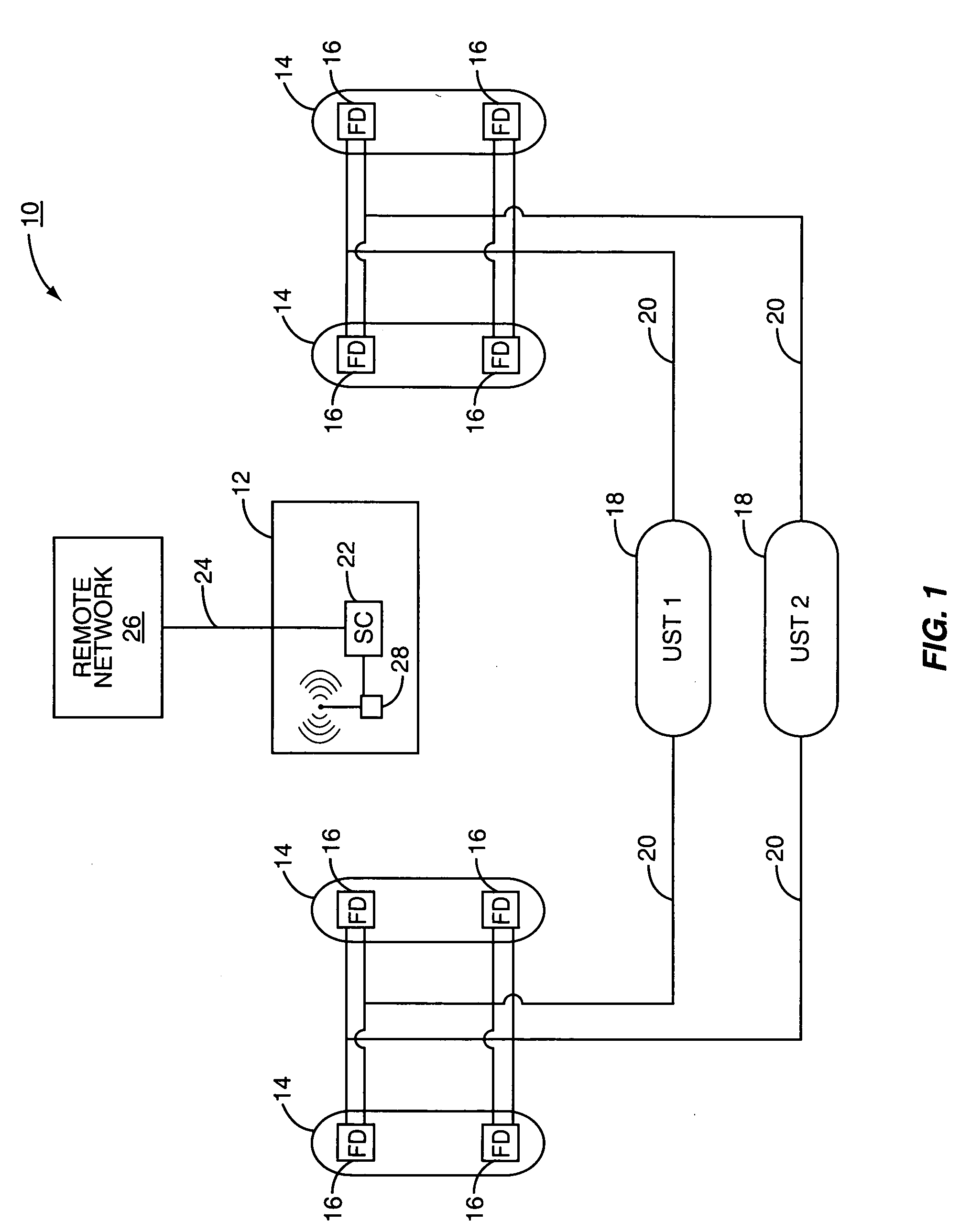
[0025] The present invention associates wireless transceivers with probes in a fueling environment. To help ensure that the wireless signals being generated by the wireless transceivers reach a wireless transceiver associated with a fueling environment site communicator, the present invention positions repeaters at various locations within the fueling environment. The repeaters receive the signals from the probe transceivers and...


PUM


Abstract

A fueling environment is equipped with leak detection probes and liquid level probes. Each of the probes is associated with a wireless transceiver. The wireless transceivers send probe data to a site communicator wireless transceiver. To ensure that the site communicator receives the probe data, repeaters are used within the fueling environment. The repeaters receive the probe data, and some period of time after the sensor transceivers stop transmitting, the repeaters retransmit the probe data to the site communicator. The site communicator discards duplicative information and processes the probe data as needed.

Description

FIELD OF THE INVENTION [0001] The present invention is directed to a leak detection system in a fueling environment, and, more particularly, is directed to a system that includes sensors that report wirelessly to a site controller or tank monitor in the fueling environment. BACKGROUND OF THE INVENTION [0002] Fueling environments are being subjected to increasingly rigorous statutes and regulations that prohibit fuel leaks and detail how leaks are to be detected within the fueling environment. One particular area in which leak detection is critical is in the storage tank in which the fuel is stored prior to sale. Such storage tanks, which are typically located beneath the ground, and thus, are commonly referred to as “underground storage tanks”, are typically equipped with a probe that measures the height of the fluid within the storage tank. Additionally, the probe may measure temperature, pressure, and other environmental factors that are used in determining the volume of fluid wit...

Claims


Application Information

Patent Timeline
Patent Type & Authority Applications(United States)
IPC IPC(8): G08B1/08G08B21/00
CPCH04Q9/00G08C17/02
Inventor REID, KENTLONGWORTH, JAMES J.KUNZ, DONALD A.
Owner VEEDER ROOT
Why Eureka
Try Eureka