
Method for tuning antenna module in portable wireless terminal and built-in antenna module using the same

a portable wireless terminal and antenna module technology, applied in the direction of slot antennas, antenna details, antennas, etc., can solve the problems of reducing the portability of the terminal, affecting the performance of the antenna device, and requiring many test samples for the tuning of the antenna device using variable design parameters, so as to achieve the effect of improving productivity and yield and reducing time loss

Active Publication Date: 2006-06-29
SAMSUNG ELECTRONICS CO LTD
View PDF7 Cites 13 Cited by
  • Summary
  • Abstract
  • Description
  • Claims
  • Application Information

AI Technical Summary

Benefits of technology

[0010] The present invention provides a method for tuning an antenna module in a portable wireless terminal and built-in antenna module using the same, which does not require extensive testing because a desired antenna property can be easily attained without considering variable design parameters.
[0011] Also, the present invention provides a method for tuning an antenna module in a portable wireless terminal and built-in antenna module using the same, in which a matching circuit is installed separate from a mainboard of the portable wireless terminal, to easily perform resonant frequency tuning and bandwidth tuning.
[0012] Further, the present invention provides a method for tuning an antenna module in a portable wireless terminal and built-in antenna module using the same, in which a passive element with a specific characteristic value is used to easily perform an antenna tuning for a Planar Inverted-F antenna (PIFA). The passive element is used instead of, for example, adjusting the distance between a feed pin and a ground pin.
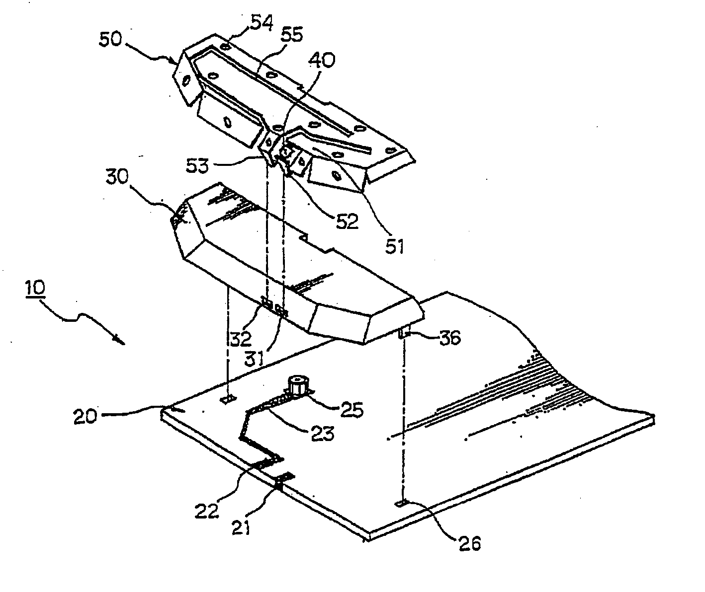
[0013] According to an aspect of the present invention, a method is provided for tuning an antenna module in a portable wireless terminal, in which the antenna module is provided with a plate type radiator in which a slot with a predetermined width is defined to form a pattern and the plate type radiator is provided with downwardly protruding feed and ground pins that are spaced apart. The method includes the step of connecting at least one passive element having a predetermined value to the radiator to optimally tune the antenna module.
[0015] According to the present invention, a matching unit, which is conventionally located on a mainboard, is installed on an antenna radiator to attain various advantages. For example, though the matching unit on the mainboard is considered as a fixed design parameter because it is hard to replace, the matching unit on the radiator can be easily replaced with another one to tune the antenna module. Therefore, the antenna tuning can be carried out conveniently and quickly while considering less variable design parameters.
[0017] Consequently, adjustment of the variable design parameters, such as the feed pin width and length, the ground pin width and length, and the distance between the feed pin and the ground pin, is minimized when tuning the antenna module. Thereby, productivity and yield are improved without frequent sample replacement and the accompanying loss of time.

Problems solved by technology

This fragility decreases the portability of the terminal.
However, the tuning of the antenna device using the variable design parameters requires many test samples.
Also, since the antenna has to be tested with respect to each variable design parameter, tuning the antenna device is a lengthy process.

Method used


Image

  • Method for tuning antenna module in portable wireless terminal and built-in antenna module using the same
  • Method for tuning antenna module in portable wireless terminal and built-in antenna module using the same
  • Method for tuning antenna module in portable wireless terminal and built-in antenna module using the same

Examples


Embodiment Construction

[0028] Reference will now be made in detail to the preferred embodiments of the present invention, examples of which are illustrated in the accompanying drawings. A detailed description of well-known features will be omitted for conciseness.

[0029] A slide-type portable wireless terminal is illustrated to describe the present invention. However, the present invention is not limited to the illustrated terminal. The present invention can be applied to various kinds of wireless devices with a plate type built-in antenna module, such as PDAs, other types of portable wireless terminals, and wireless notebooks.

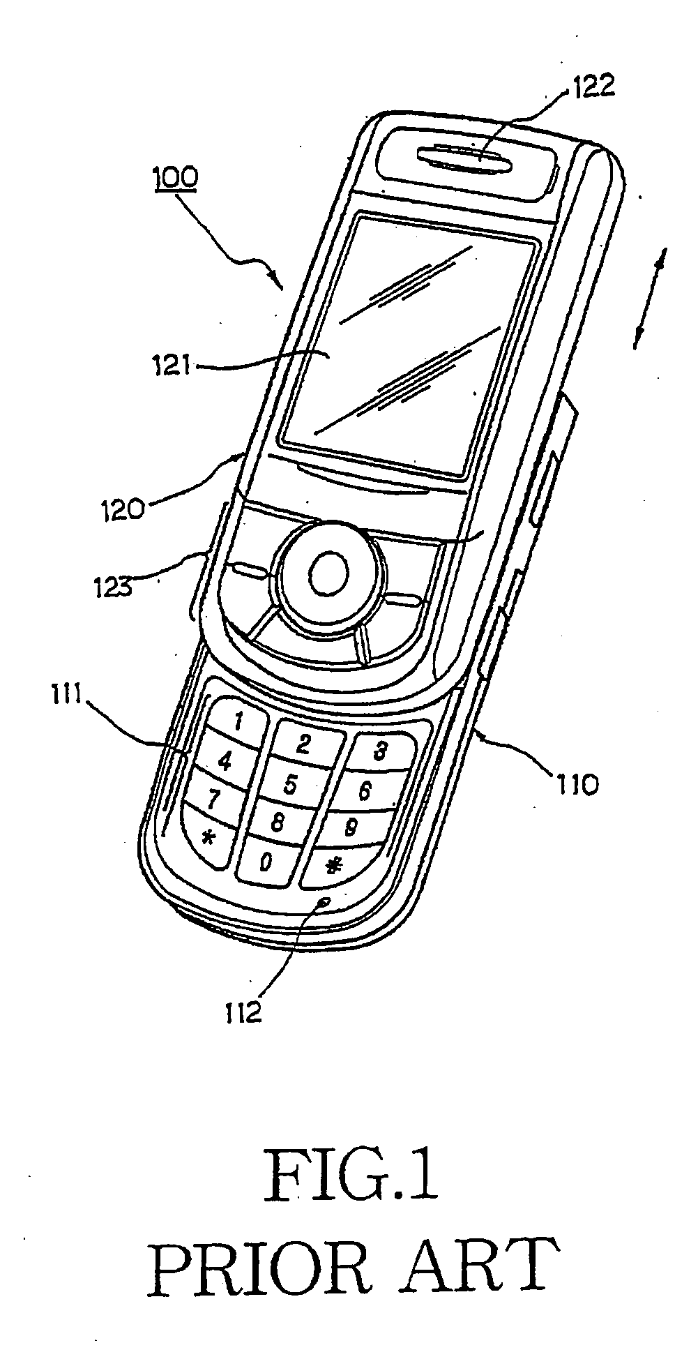
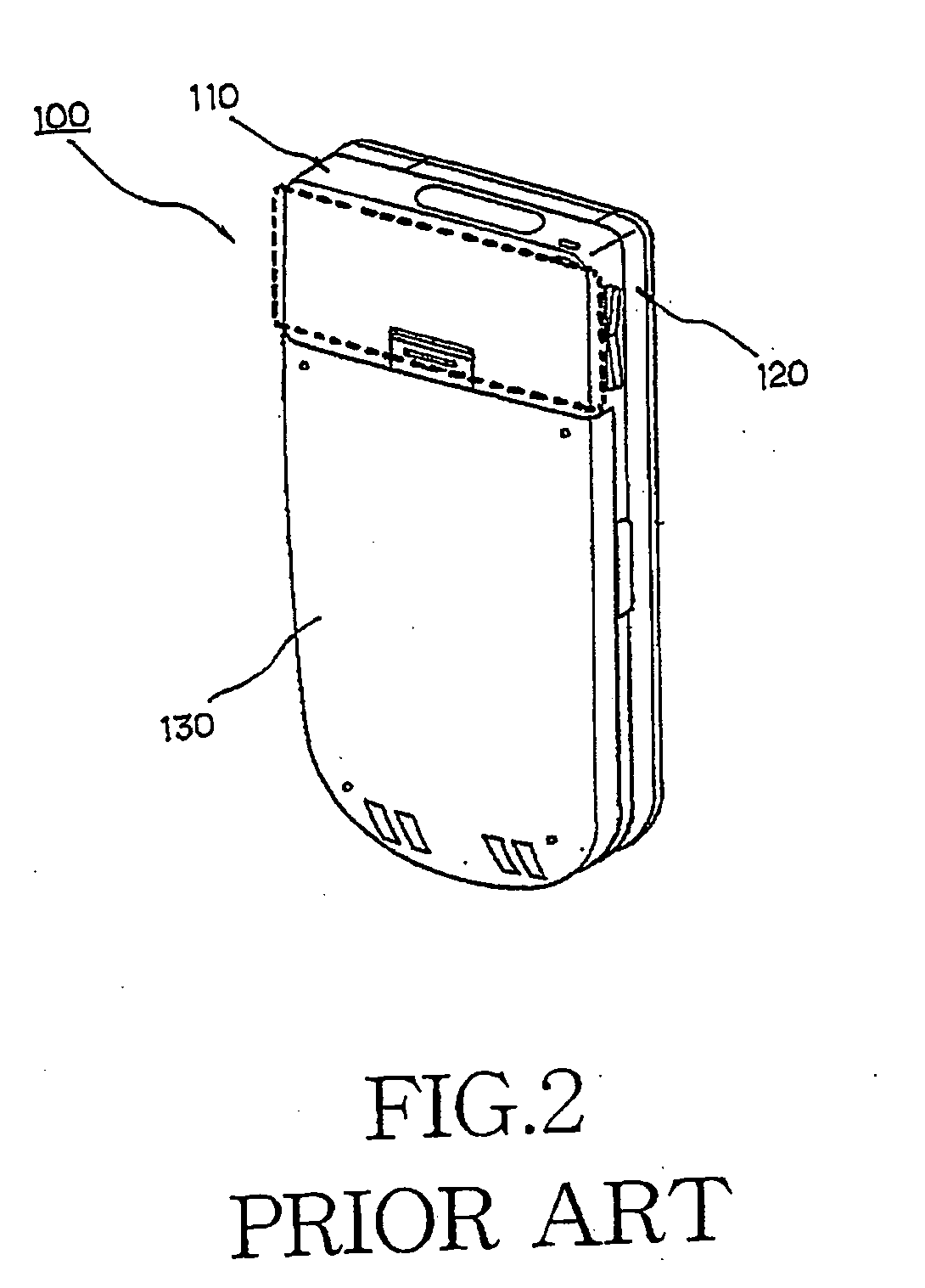
[0030]FIG. 1 is a front perspective view of a typical slide type portable wireless terminal, and FIG. 2 is a rear perspective view of a typical slide type portable wireless terminal, showing an installation location of a built-in antenna module.

[0031] Referring to FIGS. 1 and 2, a portable wireless terminal 100 such as a slide-type terminal is illustrated. The portable wireless te...


PUM


Abstract

Disclosed is a method for tuning an antenna module in a portable wireless terminal and built-in antenna module using the same. According to the method and built-in antenna module, the built-in antenna module is provided with a plate type radiator defining a slot with a predetermined width to form a pattern. The plate type radiator is provided with downwardly protruded feed and ground pins that are spaced apart, and at least one passive element having a predetermined value is connected to the radiator to optimally tune the antenna module. Therefore, various frequency response properties of the built-in antenna module can be attained by altering such a passive element as a variable design parameter without changing the radiator. Also, this construction can take the place of a matching circuit in a signal line, such that radiation performance can be increased without insertion loss.

Description

PRIORITY [0001] This application claims priority under 35 U.S.C. §119 to an application entitled “Method for Tuning Antenna Property in Portable Wireless Terminal and Built-In Antenna Module Using Thereof” filed in the Korean Intellectual Property Office on Dec. 24, 2004 and assigned Serial No. 2004-112163 and the contents of which are herein incorporated by reference. BACKGROUND OF THE INVENTION [0002] 1. Field of the Invention [0003] The present invention relates to a built-in antenna module of a portable wireless terminal and, more particularly, to a method for tuning an antenna module in a portable wireless terminal and built-in antenna module using the same, in which a matching unit is added to facilitate the design of a Planar Inverted-F Antenna (PIFA). [0004] 2. Discussion of the Prior Art [0005] Mobile wireless terminals, such as Personal Communication Service (PCS) terminals, Digital Cellular System (DCS) terminals, Global Positioning System (GPS) terminals, Personal Digita...

Claims


Application Information

Patent Timeline
Patent Type & Authority Applications(United States)
IPC IPC(8): H01Q1/24
CPCH01Q1/243H01Q9/0421H01Q9/0442
Inventor JANG, CHANG-WON
Owner SAMSUNG ELECTRONICS CO LTD
Learn More