Element substrate for recording head, recording head, and recording apparatus

Active Publication Date: 2006-06-29
CANON KK
View PDF12 Cites 10 Cited by
  • Summary
  • Abstract
  • Description
  • Claims
  • Application Information

AI Technical Summary

Benefits of technology

[0020] With this structure, the number of terminals of the inkjet recording head is redu

Problems solved by technology

These techniques are inevitable for achieving a high-speed and high-resolution printing operation, and reducing the sizes of these components is a development issue from now on.
A multiple of types of inkjet recording heads have been developed so as to meet the requirements of the performances of the main bodies of printers having the respective recording heads mounted thereon, and control circuits of the recording heads become complicated.
In order to make high-speed and high-resolution inkjet recording heads including these circuits and having a multiple of ink channels, optimization of each control circuit needed for the recording head is an issue of the inkjet-recording-head element substrate.
Unfortunately, this arrangement causes an increase in the number of terminals in the same manner as in the foregoing patent document, thereby preventing configuration of a low cost inkjet recording head because the number of terminals of the inkjet recording head increases.

Method used


Image

  • Element substrate for recording head, recording head, and recording apparatus
  • Element substrate for recording head, recording head, and recording apparatus
  • Element substrate for recording head, recording head, and recording apparatus

Examples


first embodiment

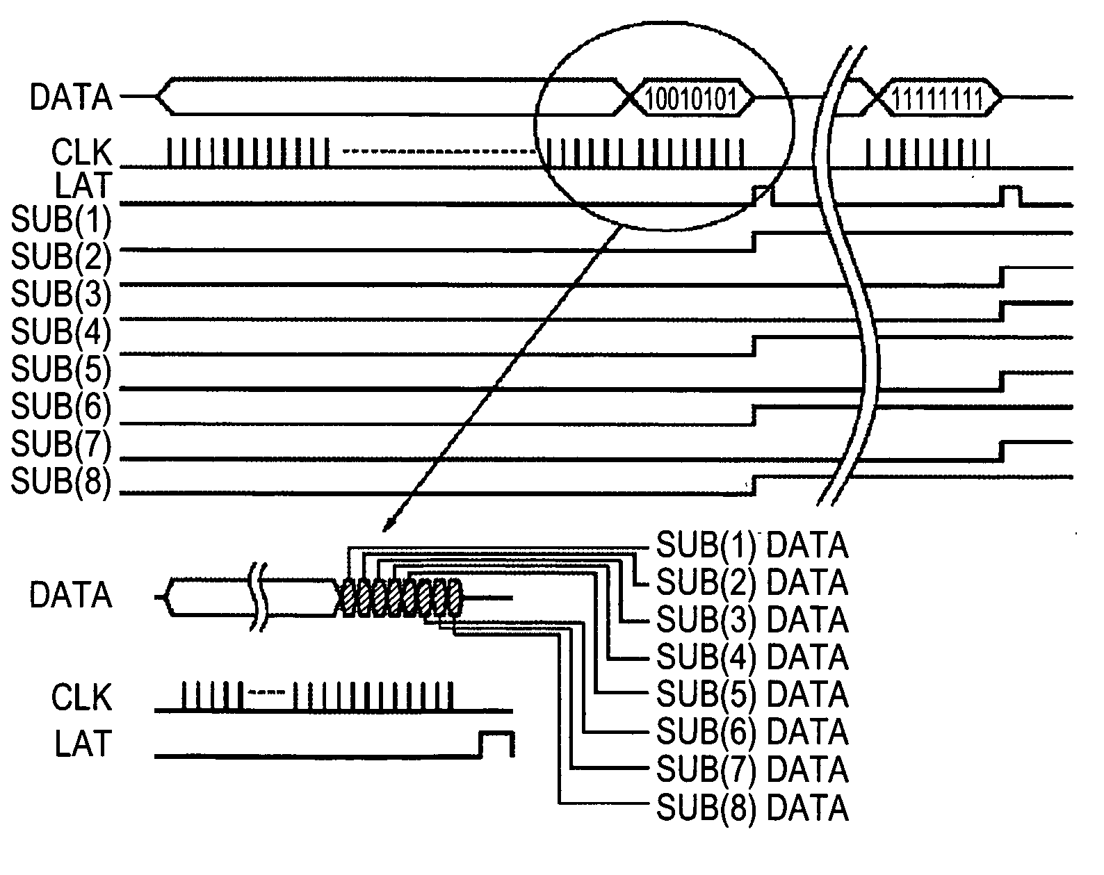
[0072]FIG. 1 is a diagrammatic view illustrating a characteristic part of the structure of a recording head according to a first embodiment of the present invention. As an example structure of the recording head, on the inkjet-recording-head element-substrate 1, a plurality of the electrothermal converters (e.g., resistive elements) 2 for discharging ink and discharge ports arranged so as to correspond to the respective electrothermal converters, and the ink supply port 14 for feeding ink to the discharge ports are formed. The ink supply port 14 is formed by anisotropic etching or sandblasting. As described above, the electrothermal converters are connected to the control circuit so as to be selectively driven in response to recording image information.

[0073] In order to clearly depict the structure of the heating devices (the sub-heaters), the functional driver row (the driver row) such as the MOS-FET row for selectively controlling drive of the conversion members 2, the circuit w...

second embodiment

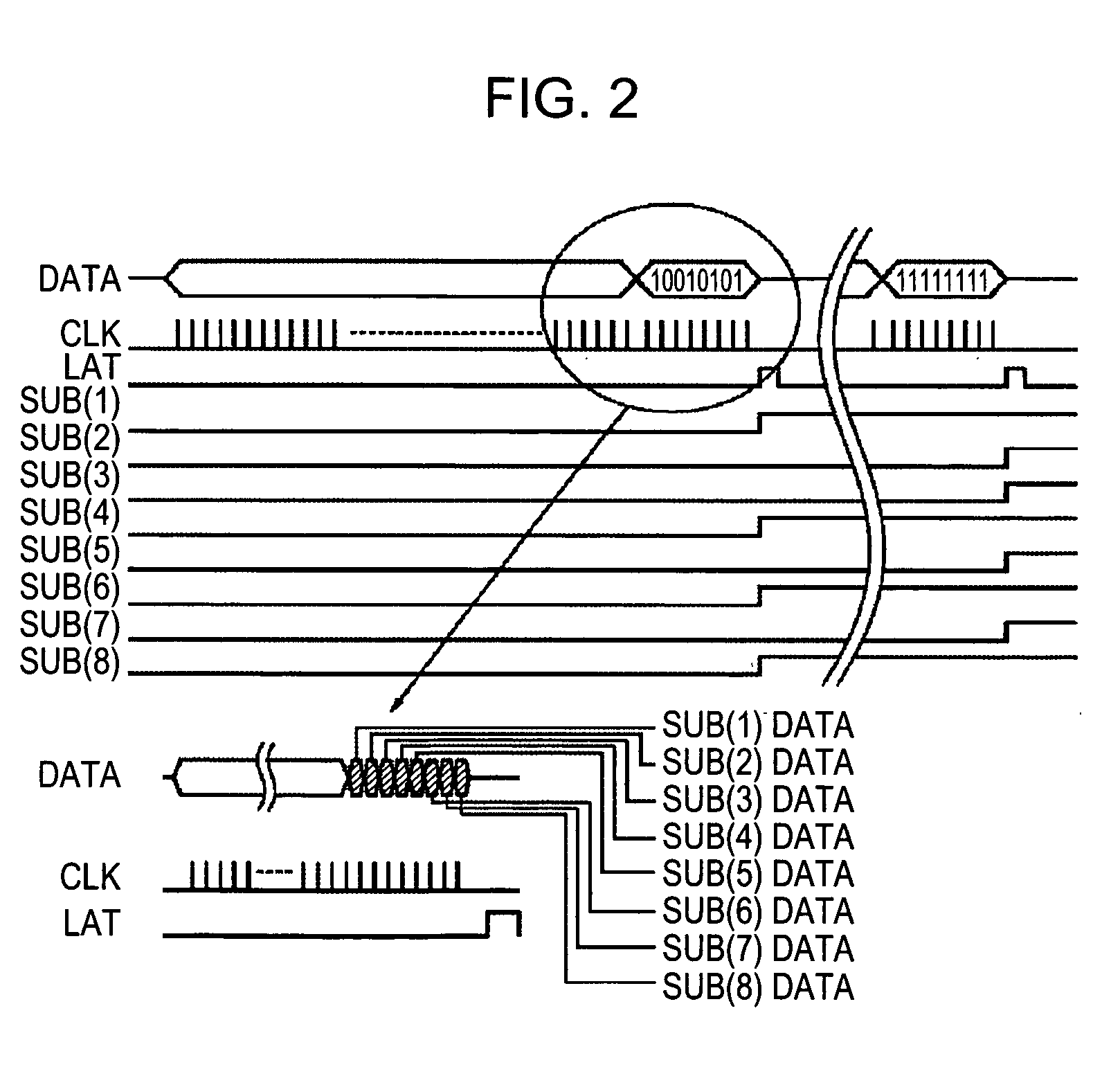
[0082]FIG. 3 is a layout diagram of a partial circuit of the recording head according to a second embodiment of the present invention, illustrating the circuit configuration on the element substrate depending on the structure of the recording head according to the related art shown in FIG. 14. In the figure, the plurality of electrothermal converters (in the figure, formed in a single row) 2 and the ink supply port 14 are shown. The electrothermal converter row 2 is arranged so as to face the ink supply port 14. Similar to those of the related art shown in FIG. 14, the electrothermal converters are connected to the control circuit so as to be selectively driven in response to recording image information. As described above, the functional element row (the driver row) 3 composed of, e.g., MOS-FETs, for individually controlling drive of the electrothermal converters, the common electrodes VH 4 and GNDH 5, and the wiring lines 9 are arranged.

[0083] The common electrodes VH and GND may...

third embodiment

[0089]FIG. 4 is a layout diagram of a partial circuit of an example circuit configuration of a recording head according to a third embodiment of the present invention. The circuit configuration is limited so as to illustrate functions of the inkjet recording head in comparison to those shown in FIG. 3. With this structure, the electrothermal converters respectively corresponding to large and small droplets are not concurrently driven. Also, input terminals for individual on / off information and those for a time-division drive and the other functional information are separated from each other. With this structure, the signal input terminals are separated depending on their functions, thereby easily making clear drive-signal processing systems of the controller of the printer main body.

[0090] When the recording head has a plurality of feedback control functions accompanying the recording control functions, as described in the present embodiment so as to serve as independent functions,...


PUM


Abstract

The structure of a recording head and a control sequence of a recording apparatus that compensate for a change in a recording element characteristic due to a temperature change of the recording head without increasing the number of terminals of the recording head are provided. Devices for individually heating and controlling a plurality of sub-heaters on an element substrate of the recording head are arranged on an element substrate of the recording head, and digital control information for controlling these devices is inputted to the element substrate.

Description

BACKGROUND OF THE INVENTION [0001] 1. Field of the Invention [0002] The present invention relates to a recording-head element substrate, a recording head, and the control circuit configuration of a recording apparatus having the recording head mounted thereon, and more particularly, it relates to the temperature-adjusting control configuration of the recording head. [0003] 2. Description of the Related Art [0004] As an information output apparatus of a personal computer, a facsimile machine, or the like, a variety of inkjet recording apparatuses discharging ink through discharge ports arranged so as to correspond to recording elements are known. Of these recording apparatuses, a recording apparatus heating and then discharging ink has electrothermal conversion elements generating energy for discharging ink, incorporated therein so as to serve as recording elements (electrothermal converters), thereby achieving a high-density and high-speed recording performance and being widely avai...

Claims


Application Information

Patent Timeline
IPC IPC(8): B41J29/38
CPCB41J2/04528B41J2/04533B41J2/04541B41J2/04543B41J2/04563B41J2/0458
Inventor HAYASAKI, KIMIYUKI
Owner CANON KK
Why Eureka
Try Eureka