
Technique for increased exposure range in image sensors

a technology of image sensor and exposure range, which is applied in the direction of exposure control, color signal processing circuit, instruments, etc., can solve the problems of inability to capture multiple images that are identical, limited dynamic range of digital image sensor, and high probability of multiple images being captured by the same photographer

Inactive Publication Date: 2006-06-29
INTEL CORP
View PDF16 Cites 69 Cited by
  • Summary
  • Abstract
  • Description
  • Claims
  • Application Information

AI Technical Summary

Problems solved by technology

The dynamic range of a digital image sensor is more limited.
One problem with capturing multiple images is that the camera moves in the hands of the photographer.
A second problem arises when a scene or a subject to be captured contains elements that are moving.
In such cases, it is highly unlikely that a photographer will capture multiple images that are identical to each other.
This complicates or eliminates the possibility of blending images of the scene.
However, in some flash designs it is difficult to control the amount of light generated by the flash because once the flash is triggered it continues to provide illumination to the scene until the flash finishes.

Method used


Image

  • Technique for increased exposure range in image sensors
  • Technique for increased exposure range in image sensors
  • Technique for increased exposure range in image sensors

Examples


Embodiment Construction

[0010] In the following detailed description, reference is made to the accompanying drawings which form a part hereof, and in which is shown by way of illustration specific embodiments in which the invention may be practiced. It is to be understood that other embodiments may be used and structural and logical changes may be made without departing from the scope of the present invention.

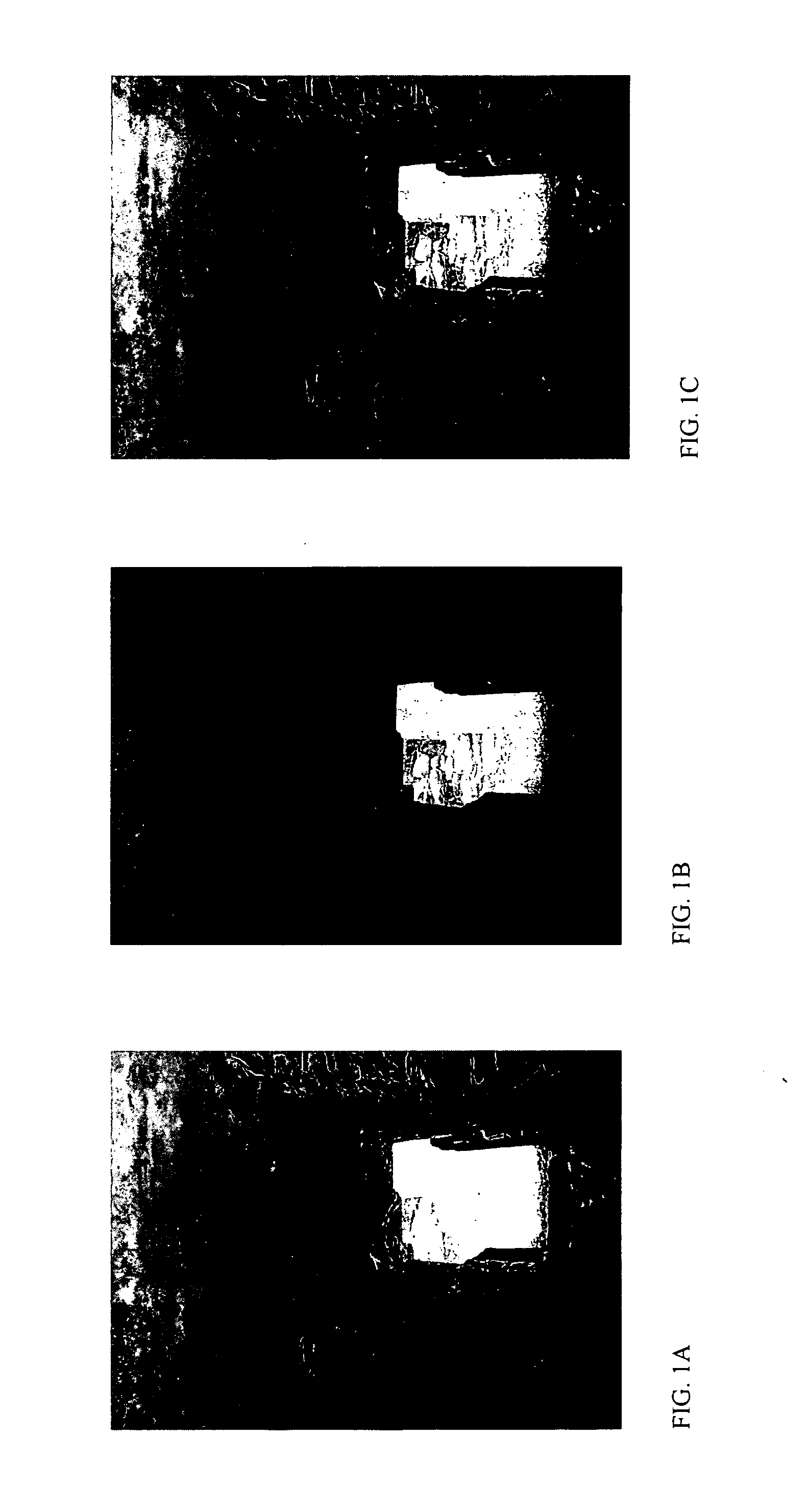
[0011] This document describes systems and methods to improve the range of exposure for image sensors. As discussed previously for high contrast scenes, the dynamic range of a standard image sensor forces a camera user to choose to capture either the detail in dark areas or to choose to capture the detail in the light areas of the scene. A common technique in film photography is to improve the range of exposure of an image by “bracketing” an image. Bracketing an image involves taking multiple exposures of the image. Usually three exposures are taken in quick succession. One picture is exposed with th...


PUM


Abstract

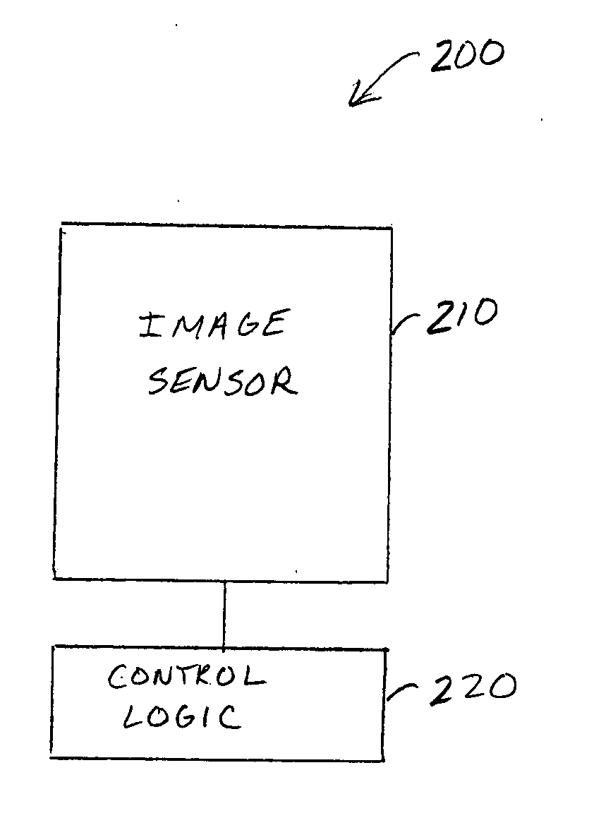
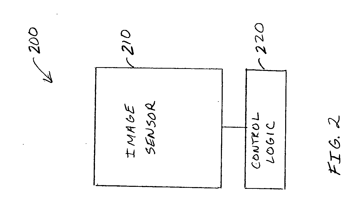
An apparatus comprising an image sensor and a control logic circuit. The image sensor includes at least a first pixel array and a second pixel array, wherein at least some of the pixels of the first pixel array are interspersed over an image sensing area with pixels of the second pixel array. The control logic circuit is operable to control durations of exposure of the first pixel array and the second pixel array independently.

Description

BACKGROUND [0001] A standard digital image sensor is a homogenous array of light sensitive cells called pixels. The pixels can include either charge coupled devices (CCD) or complimentary metal oxide semiconductor (CMOS) devices. The individual pixels are monochrome and only detect light, not color. To provide color images, the monochrome pixels are covered with color filters. Typically filters that pass red, green, and blue light are arranged on a cluster of pixels. Color for each pixel cluster is then determined using a coding scheme such as Bayer encoding. Digital camera image sensors do not have a mechanical shutter, but use an “electronic shutter.” Photons incident to the pixels create charge on the pixels. The brighter the light that is incident to a pixel, the more charge that accumulates on the pixel. This charge results in a voltage on the pixel that can be sampled and quantized. The brightness of the resulting image is related to the voltage sampled on the pixel. An electr...

Claims


Application Information

Patent Timeline
Patent Type & Authority Applications(United States)
IPC IPC(8): H04N5/335G06F3/14H04N23/12
CPCH04N3/155H04N5/35554H04N25/583
Inventor MCGOWAN, STEVEN B.
Owner INTEL CORP
Learn More