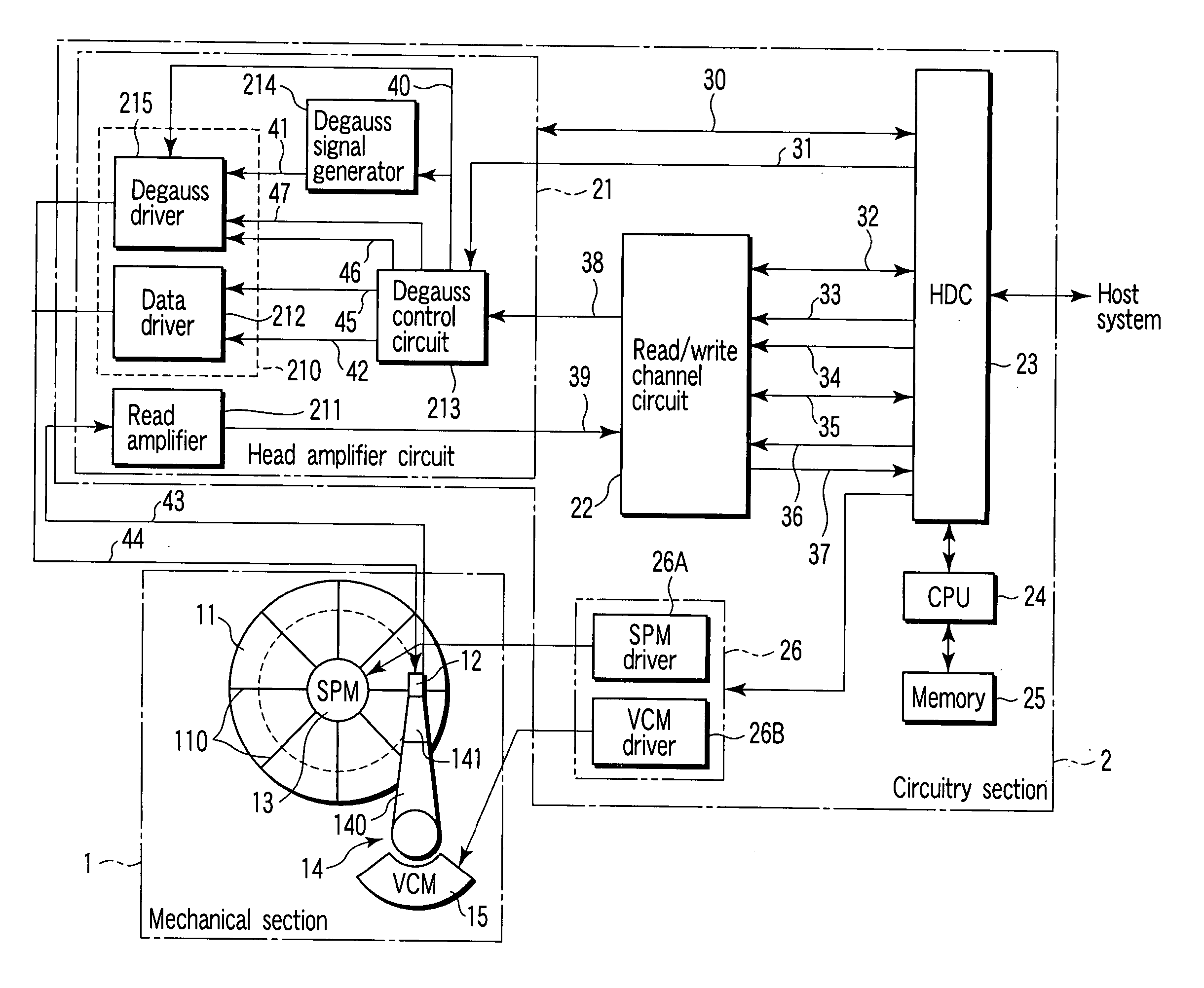
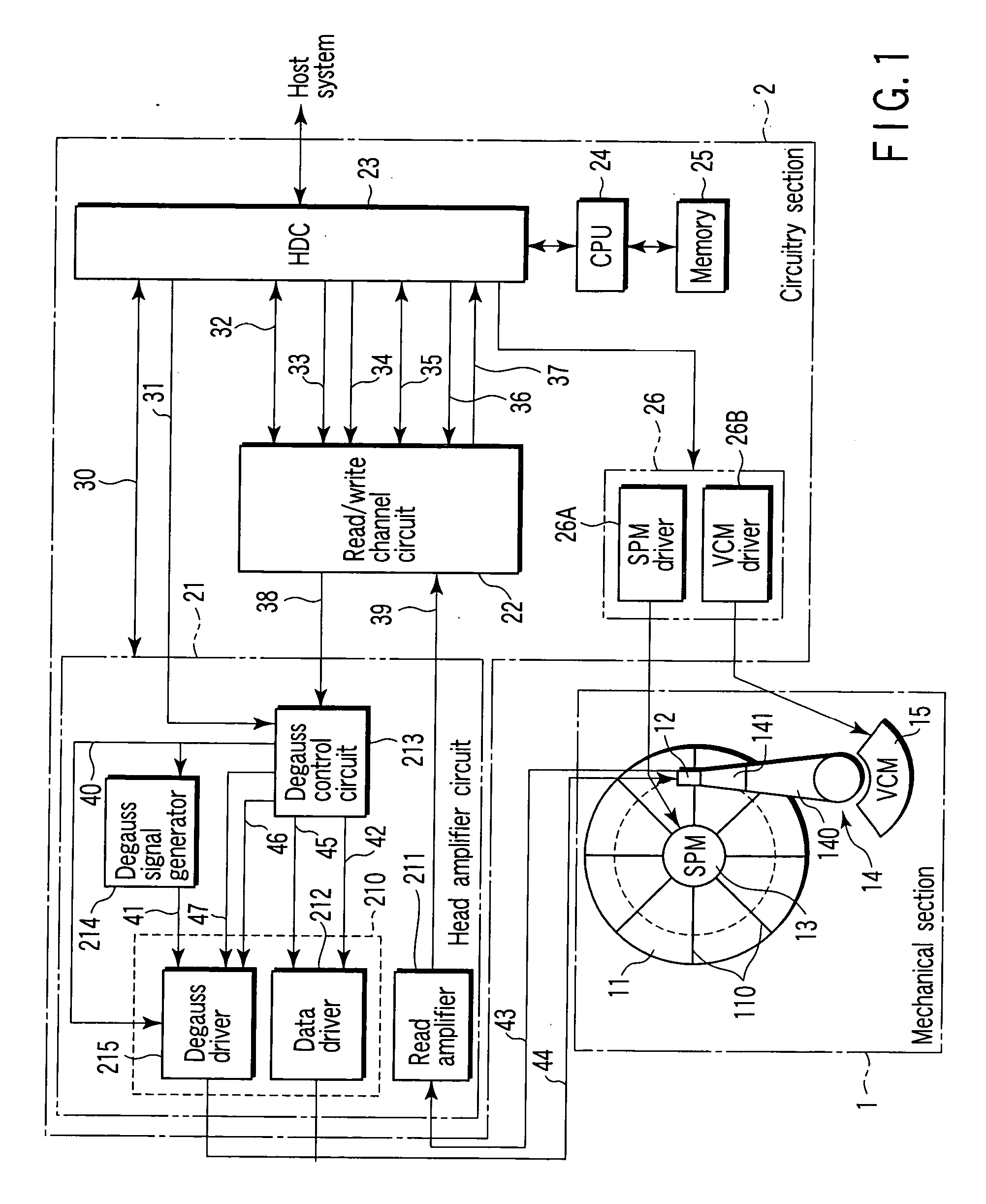
Head amplifier circuit with function for degaussing residual magnetism of recording head
a technology of amplifier circuit and residual magnetism, which is applied in the field of hard disk drive with recording head, can solve the problem that the prior art cannot completely eliminate the residual magnetism of recent magnetic heads for high-density recording
- Summary
- Abstract
- Description
- Claims
- Application Information
AI Technical Summary
Benefits of technology
Problems solved by technology
Method used
Image

Examples
third embodiment
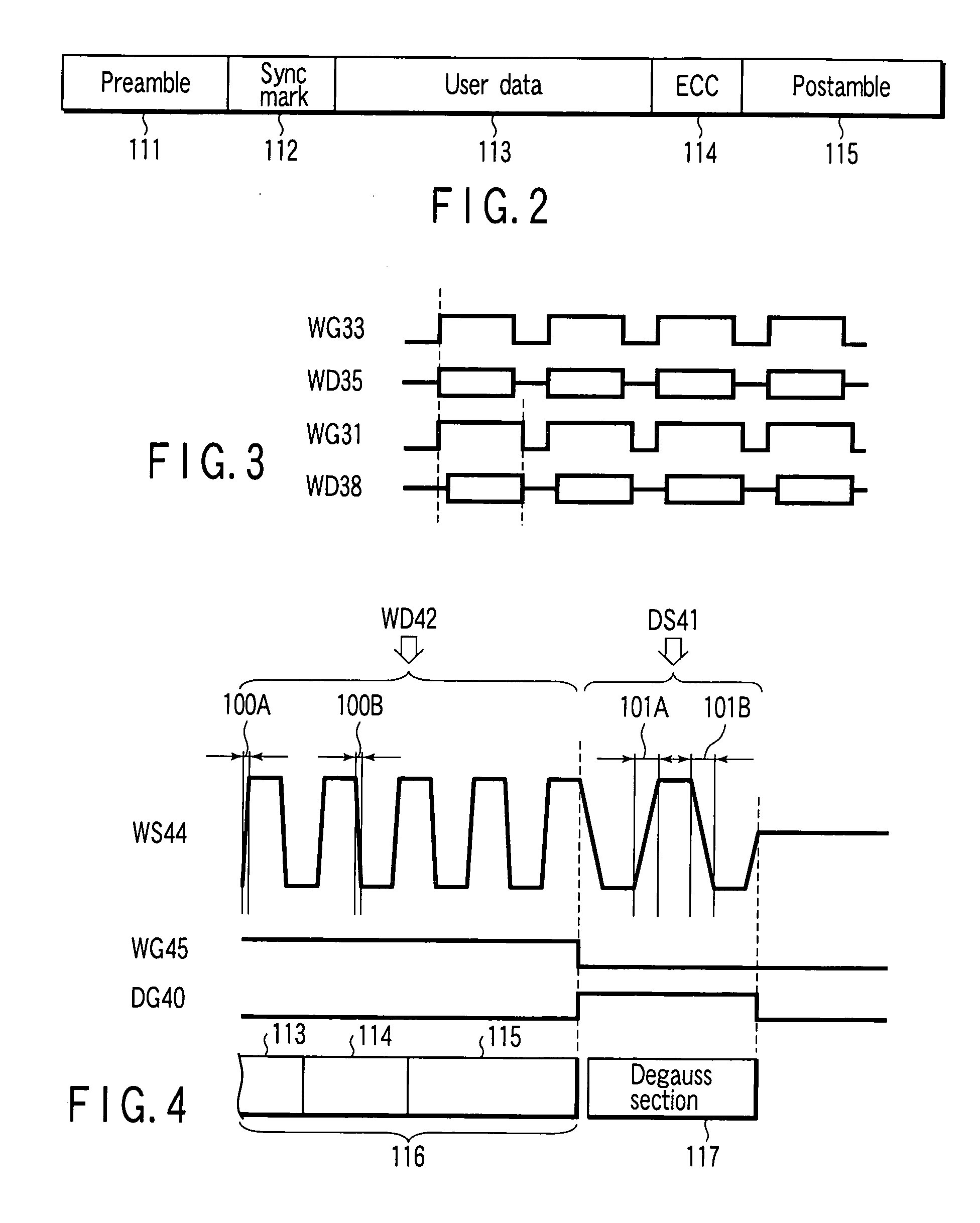
[0064] Referring to FIG. 8, a third modification of the embodiment will be described. FIG. 8 is a timing chart illustrating the relationship between WS 44, WG 45 and WG 47 in relation to a data format. Like the second modification, the third modification is characterized in that part of the end portion of the postamble 115 in the write data section 116 is used as the degauss section 117. The third modification differs from the second modification in that in the former, the data write driver 212 and degauss write driver 215 generate WS 44 using WD 42 and WD 46 corresponding to WD 38 output from the read / write channel circuit 22 to the degauss control circuit 213, respectively.
[0065] Accordingly, in the third modification, when WG 31 is switched from the active state to the inactive state by the HDC 23 at some portion of the postamble 115, not only WG 45 but also WG 47 are controlled by the degauss control circuit 213. Specifically, the degauss control circuit 213 simultaneously swit...
fifth embodiment
[0070] Referring to FIG. 10, a fifth modification of the embodiment will be described. FIG. 10 is a timing chart similar to FIG. 6, in which the relationship between WS 44, WG 45 and DG 40 is shown in relation to a data format. The fourth modification is characterized in that the wave of WS 44 generated by the degauss write driver 215 when DG 40 is active is not a square wave but a sine wave. In this case, even if the frequency of WS 44 when DG 40 is active is equal to that in, for example, the first modification (see FIG. 6), Tr 101A and Tf 101B of WS 44 can be made longer than in the first modification, as is apparent from FIG. 10. As a result, the residual magnetism of the head 12 can be further efficiently eliminated. Moreover, WS 44 of a sine wave can have minimum rising / falling inclinations, and can minimize the overshoot level. This means that the occurrence itself of the residual magnetism can be suppressed.
[0071] In general, in the data-recording mode, to secure a recordin...
PUM
| Property | Measurement | Unit |
|---|---|---|
| frequency | aaaaa | aaaaa |
| recording current | aaaaa | aaaaa |
| current | aaaaa | aaaaa |
Abstract
Description
Claims
Application Information
 - R&D
- Intellectual Property
- Life Sciences
- Materials
- Tech Scout
- Unparalleled Data Quality
- Higher Quality Content
- 60% Fewer Hallucinations
Browse by: Latest US Patents, China's latest patents, Technical Efficacy Thesaurus, Application Domain, Technology Topic, Popular Technical Reports.
© 2025 PatSnap. All rights reserved.Legal|Privacy policy|Modern Slavery Act Transparency Statement|Sitemap|About US| Contact US: help@patsnap.com