Catheter tip and method of attaching a catheter tip to a catheter shaft

a catheter shaft and catheter tip technology, applied in the direction of catheters, etc., can solve the problems of insufficient bonding strength between the injection molded tip and the end of the shaft, unacceptably high scrap rate, and inability to provide the process. less than desirable

Inactive Publication Date: 2006-06-29
FORSBERG ANDREW
View PDF7 Cites 62 Cited by
  • Summary
  • Abstract
  • Description
  • Claims
  • Application Information

AI Technical Summary

Benefits of technology

[0008] In one embodiment, the distal end of the shaft has a lap joint area and the tip is adapted to be bonded over the lap joint area. In one embodiment, the collar portion is adapted to abut against, and bond with, a lap joint face. In one embodiment, the second outside diameter is less than an extruded outside diameter of the shaft.
[0009] The present invention, in one embodiment, is a method of bonding a shaft tip to a distal end of a catheter or sheath shaft. The method includes providing a shaft with an initial outside diameter and then forming a lap joint area in the distal end of the shaft. The method also includes molding the tip over the lap joint area. The tip includes a collar at a proximal end of the tip. Finally, the method includes reducing the initial outside diameter of the shaft down to a finished outside diameter.
[0010] In one embodiment of the method, the collar has an outside diameter that is greater than the finished outside diameter. In one embodiment, the outside diameter of the collar is also less than the initial outside diameter of the shaft.

Problems solved by technology

Unfortunately, this is labor intensive and results in an unacceptably high scrap rate.
However, this often resulted in inadequate bond strength between the injection molded tip and the end of the shaft.
Unfortunately, this process also provided less than desirable results.
For instance, the tip material, when injected into the mold, has very little thermal mass and, as a result, often does not contain enough energy to adequately melt the shaft material to allow sufficient mixing between the two materials to form a sufficiently strong bond.
Another problem with insert molding is that the shutoff between the mold steel and the shaft is difficult to achieve.
Often this flash will erode or otherwise deform the outer distal surface of the shaft, resulting in scrap.
Unfortunately, high clamping pressures tend to crimp or otherwise deform the distal end of the shaft.
This reduces the surface area available for the tip to bond to the shaft and results in inadequate bond strength and scrap.
Additionally, it also creates an imperfection in the surface finish that may affect shaft functionality.

Method used


Image

  • Catheter tip and method of attaching a catheter tip to a catheter shaft
  • Catheter tip and method of attaching a catheter tip to a catheter shaft
  • Catheter tip and method of attaching a catheter tip to a catheter shaft

Examples


Embodiment Construction

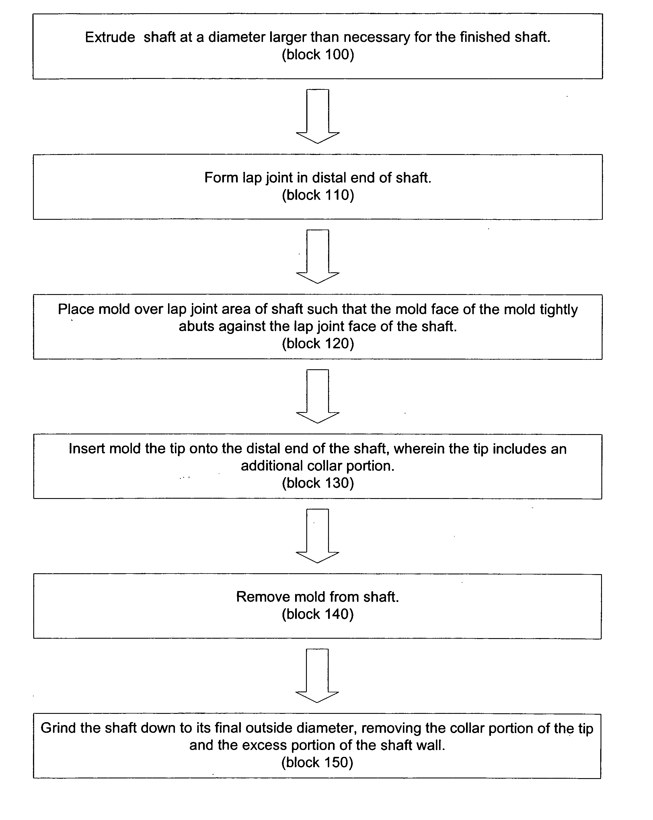
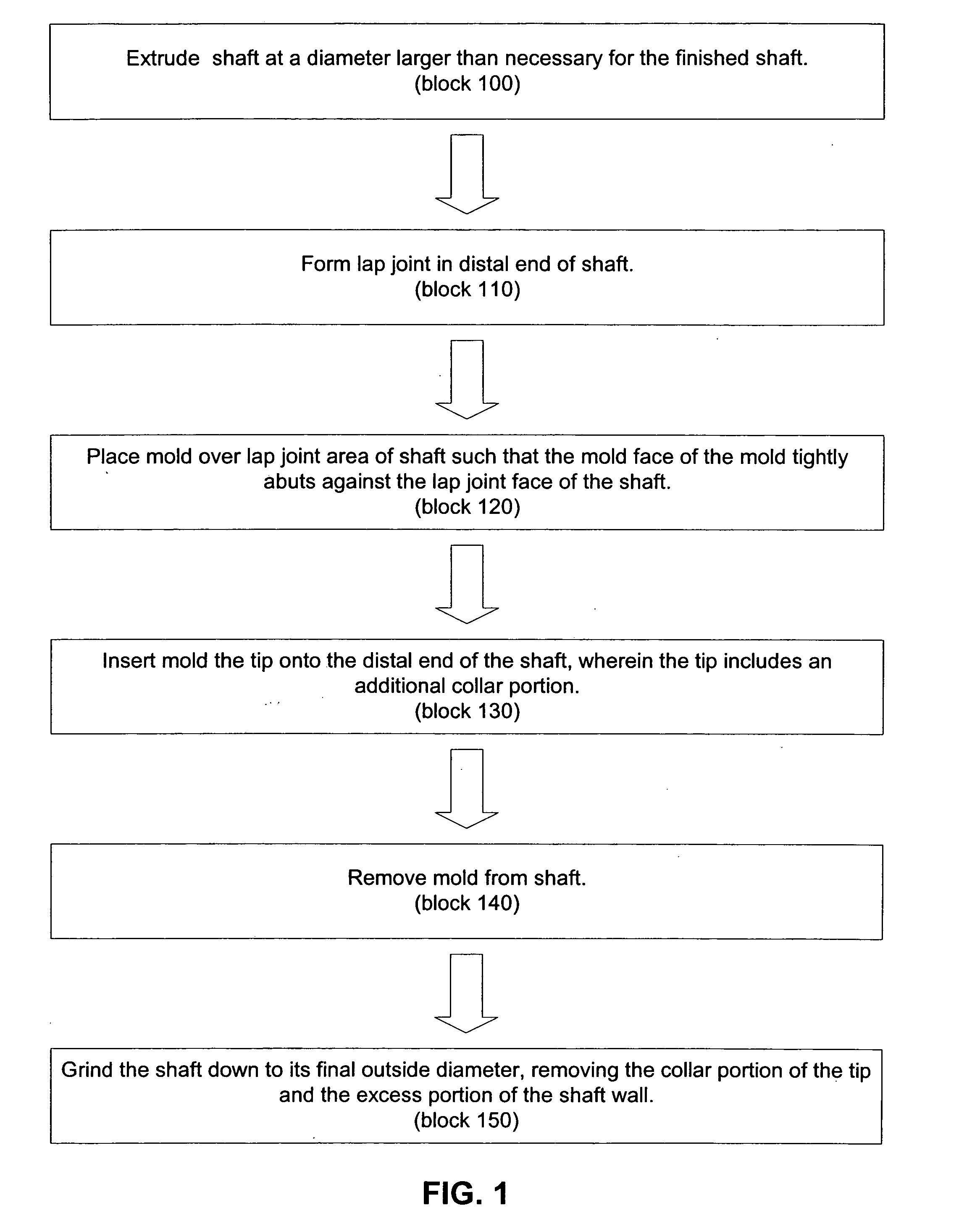
[0024] The present invention, in one embodiment, is a method of attaching or bonding a shaft tip to a catheter or sheath shaft. The method is advantageous because it is less labor intensive than prior art methods and results in less scrap. Throughout this specification, the term shaft is meant to include, without limitation, shafts for catheters, sheaths and similar medical equipment.

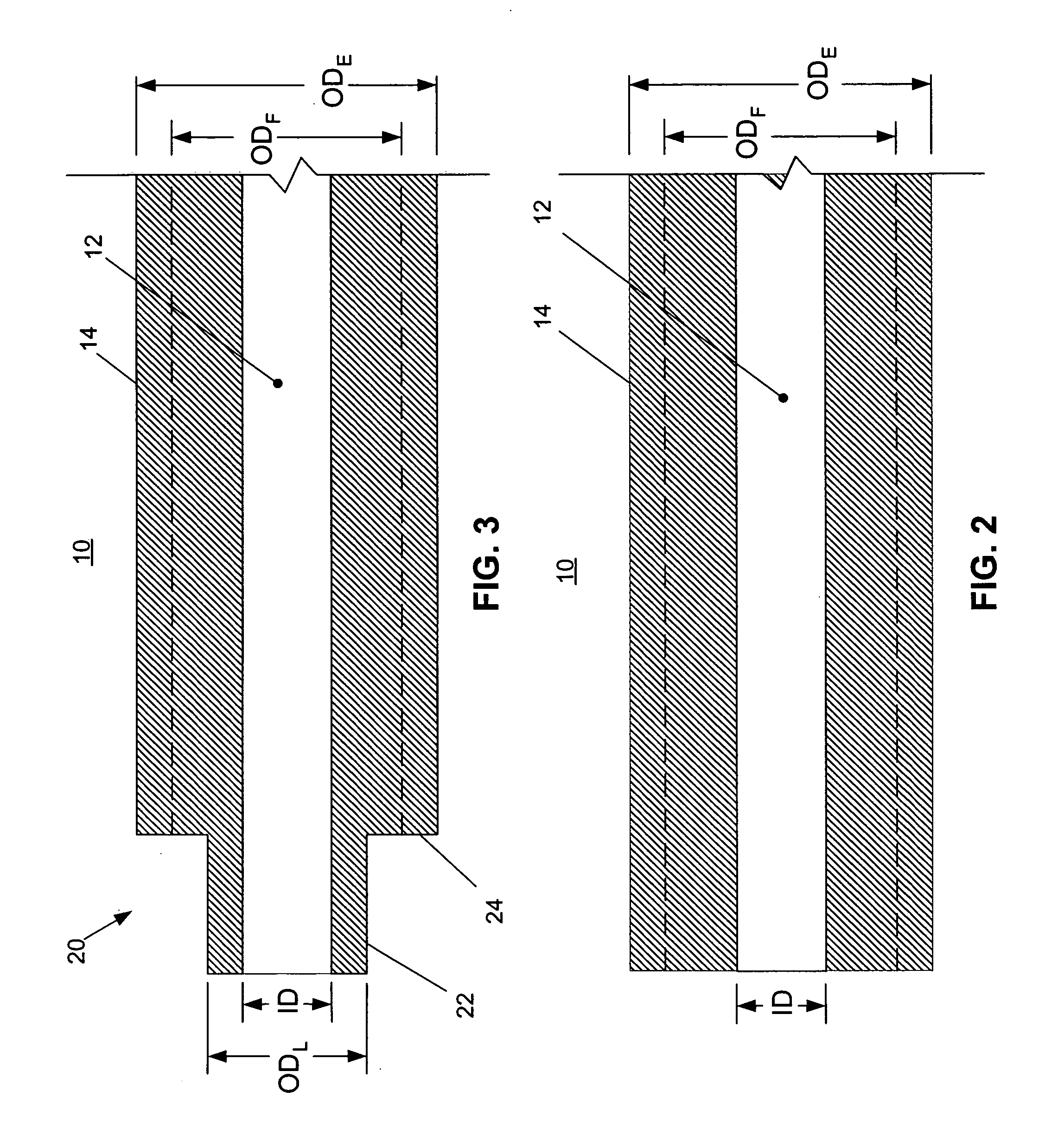
[0025] For a detailed discussion of one embodiment of the invention, reference is now made to FIGS. 1-5. FIG. 1 is a flow chart outlining the procedures comprising a method of attaching or bonding a shaft tip to a catheter or sheath shaft. FIGS. 2-5 are longitudinal sectional elevations of a distal end of a shaft 10 at the various stages of the manufacturing method, wherein the shaft 10 includes a central lumen 12 defined by a shaft sidewall 14.

[0026] As indicated in FIGS. 1 and 2, the shaft 10 is extruded such that the shaft's extruded outside diameter ODE is larger than the shaft's finished outside ...


PUM

PropertyMeasurementUnit
diameteraaaaaaaaaa
areaaaaaaaaaaa
bond strengthaaaaaaaaaa

Abstract

The present invention is a method of bonding a shaft tip to a distal end of a catheter or sheath shaft. The method includes extruding a shaft to have an initial outside diameter that is greater than an outside diameter the shaft will have when finished. A lap joint area is then ground into the distal end of the shaft. The tip is then insert molded over the lap joint area. The tip includes a collar at a proximal end of the tip that provides additional thermal mass to facilitate the bonding of the tip to the shaft. The shaft is then ground from its initial outside diameter to its finished outside diameter.

Description

FIELD OF THE INVENTION [0001] The present invention relates to catheters and sheaths and methods of making catheters and sheaths. More particularly, the present invention relates to tips for the shafts of catheters and sheaths and methods of attaching tips to such shafts. BACKGROUND OF THE INVENTION [0002] There is a need for catheter and sheath shafts having complex tip geometries. In the past, such shafts were produced by thermoforming the shaft tip in several discrete operations. Unfortunately, this is labor intensive and results in an unacceptably high scrap rate. [0003] In an effort to find a replacement process for thermoforming, the inventor of the present invention attempted to injection mold the tip separately and then bond the tip to the end of a shaft. However, this often resulted in inadequate bond strength between the injection molded tip and the end of the shaft. [0004] In another effort, the inventor of the present invention also attempted to insert mold the shaft tip...

Claims


Application Information

Patent Timeline
Patent Type & Authority Applications(United States)
IPC IPC(8): A61M25/00
CPCA61M25/001A61M25/0069
Inventor FORSBERG, ANDREW
Owner FORSBERG ANDREW
Why Eureka
Try Eureka