Linking element for dynamically stabilizing a spinal fixing system and spinal fixing system comprising same

a dynamic stabilization and linking element technology, applied in the field of spinal systems for linking the vertebrae, can solve the problems of difficult introduction of the band, insufficient effective distance between the screws after tensioning the band, and insufficient and achieve the effect of small volume and desired resistance to compression and extension

Inactive Publication Date: 2006-06-29
NORGINE VENTURES BV +1
View PDF14 Cites 407 Cited by
  • Summary
  • Abstract
  • Description
  • Claims
  • Application Information

AI Technical Summary

Benefits of technology

[0018] The present invention aims to overcome the disadvantages of the prior art by proposing a linking element for a spinal fixation system which can be inserted into an implantable connecting assembly, on the head of this assembly, in a conventional manner, such as a linking rod for osteosynthesis which has a small diameter, which provides torsional return in order to incite a return to a position of equilibrium, which can be curved, which can be combined with an osteosynthesis system, and which can also be easily interchanged to perform osteosynthesis.
[0028] Advantageously, the linking element according to the invention is easy to insert into the receiving means of an implantable connecting assembly of known type. The placement of the linking element according to the invention does not involve the use of an implant specifically designed for this. The implant technique is therefore the same as for fusion.
[0029] Advantageously too, the structure of the linking element according to the invention makes it possible to obtain the desired resistance to compression and extension while requiring only a small volume. In addition, as the external diameter of the linking element according to the invention is substantially the same as that of the linking elements used for fusion, it is possible, within the same fixation system, to provide a combination of transverse links for fusion and transverse links for dynamic stabilization.
[0030] Advantageously too, the structure of the linking element according to the invention also permits torsional return in order to force a return to a defined configuration of equilibrium.
[0031] Advantageously too, the structure of the linking element according to the invention allows it to be adapted to the implantation configuration by giving it the desired shape, and in particular by curving it in advance.
[0032] Advantageously too, the structure of the linking element according to the invention permits compression and distraction directly on the screws.

Problems solved by technology

A major disadvantage of this stabilizing device is that the band has to be slid into the hole formed in the head of the pedicle screws, and also through the bearing element(s).
This first entails a difficulty, upon implantation, in passing the band through these elements, as the pedicle screws are already fixed to the vertebrae.
Introduction of the band is not easy; but it means above all that the length of the bearing element has to be chosen before the band is put in place.
It may well happen that the effective distance between the screws after tensioning of the band is not exactly the distance desired, and in this case the surgeon has no other choice than to dismantle the assembly made up of bearing element and band in order to introduce a bearing element of a different length.
In fact, this system does not afford any freedom in terms of compression or distraction between the screws after the elements have all been put in place.
Moreover, the viscoelastic material of the bearing element compresses when the band is tensioned, which further complicates the choice of length of the bearing element since this changes during tensioning of the band.
Another major disadvantage of the stabilizing device of the prior art is that the linking element takes up a considerable volume: of the order of 12.5 millimeters.
In some circumstances, it is then difficult to avoid the linking element coming into contact with bones and this contact causing great pain.
Another major disadvantage of the stabilizing device of the prior art is that the linking element does not effect any torsional return in order to oppose pivoting movements of the vertebrae about the disks.
Another major disadvantage of the stabilizing device of the prior art is that the linking element cannot be curved in order to adapt it to the natural curvature of the lumbar spine.
Another major disadvantage of the device is the impossibility of performing surgical revision to extend the assembly, or of replacing the linking element by a rigid rod in order to obtain osteosynthesis without complete removal of the material beforehand.
Another disadvantage of the device is the impossibility of combining it with a conventional osteosynthesis system.

Method used


Image

  • Linking element for dynamically stabilizing a spinal fixing system and spinal fixing system comprising same
  • Linking element for dynamically stabilizing a spinal fixing system and spinal fixing system comprising same
  • Linking element for dynamically stabilizing a spinal fixing system and spinal fixing system comprising same

Examples


first embodiment

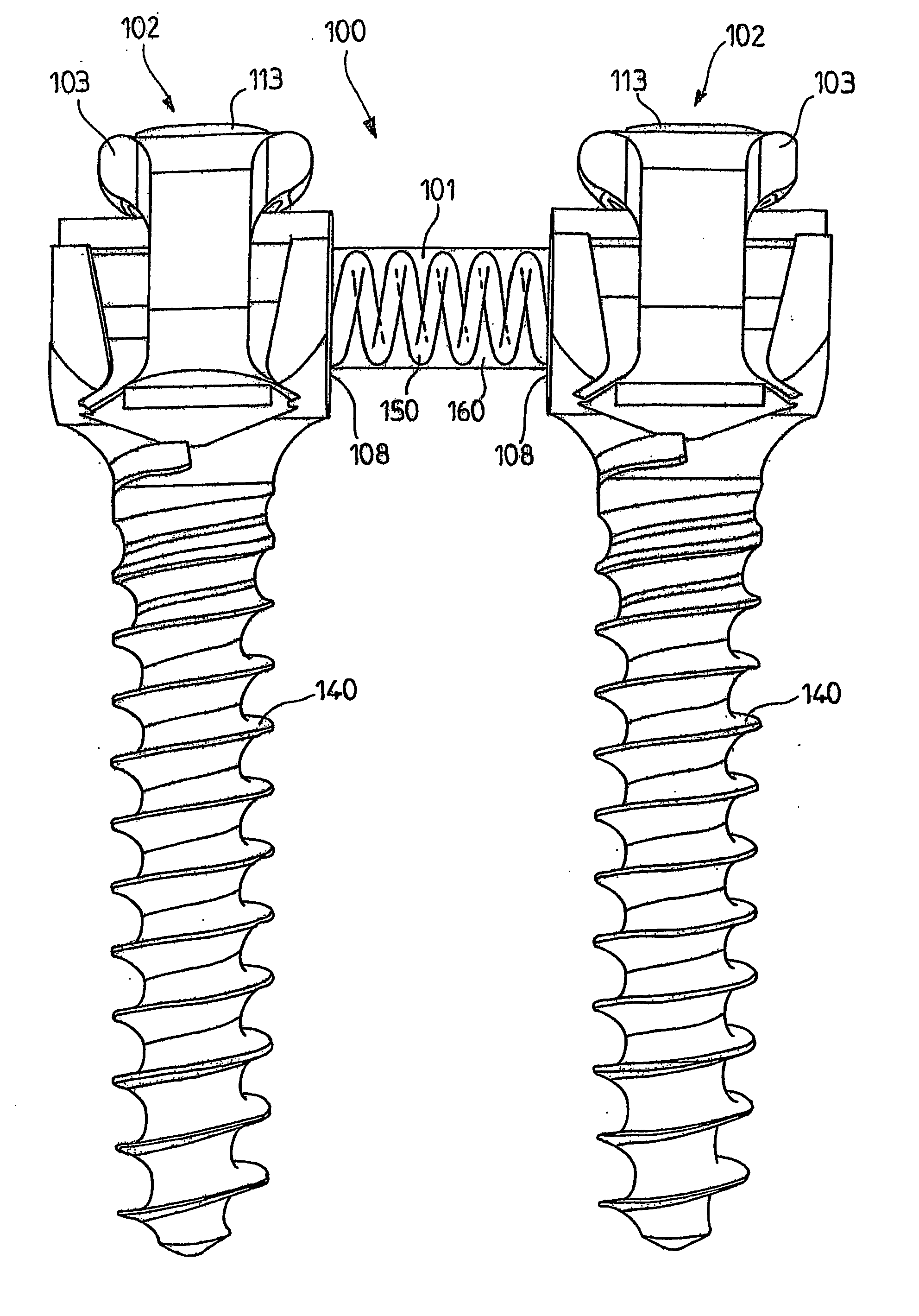
[0058] An implantable connecting assembly (102) according to the invention is an assembly such as the one which is known from international patent application WO 01 / 01873 and whose cooperation with the linking element according to the present invention is described in greater detail below, with reference to FIGS. 10 through 19.

second embodiment

[0059] An implantable connecting assembly (202) according to the invention is an assembly such as the one which is known from international patent application WO 01 / 39677 and whose cooperation with the linking element according to the present invention is described in greater detail below, with reference to FIGS. 20 through 23.

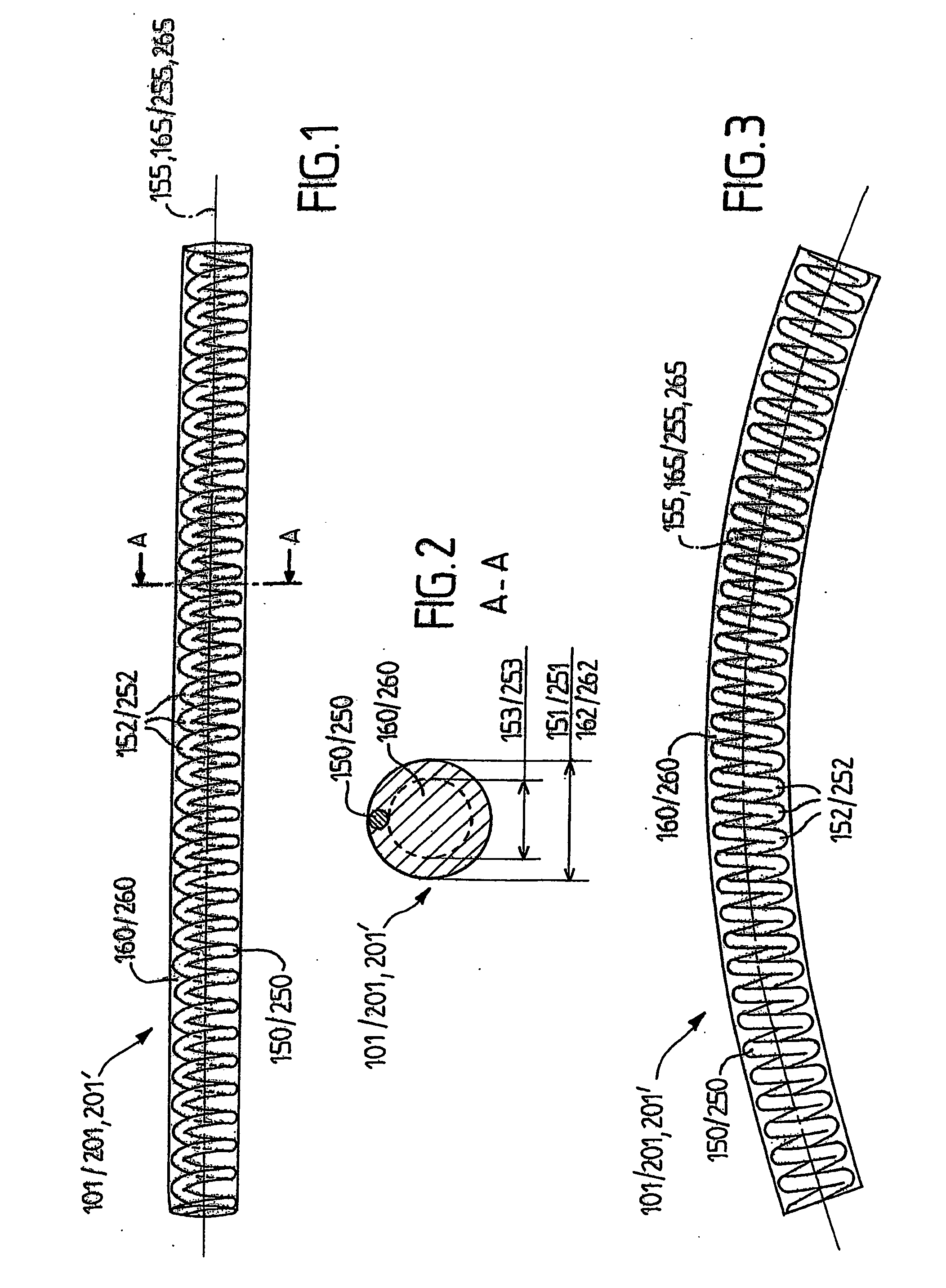
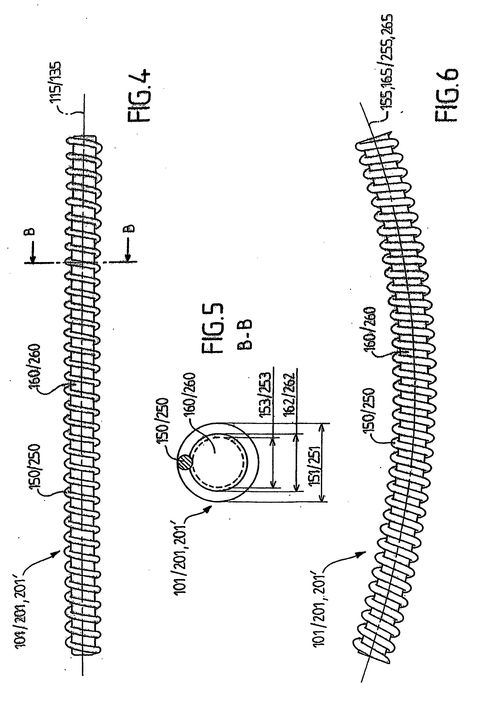
[0060] The linking element (101, 201, 201′) is substantially tubular or cylindrical and has a longitudinal axis. Its external diameter is of the order of 6 millimeters.

[0061] The linking element (101, 201, 201′) according to the invention is composed, at least partly, of:

[0062] on the one hand, a helical spring (150, 250) having an axis (155, 255) and turns (152, 252) and,

[0063] on the other hand, a support (160, 260) made of polymer material and having an axis (165, 265) substantially parallel with the axis of said helical spring (150, 250).

[0064] Said turns are at least partly embedded in at least one support (160, 260) made of polymer material.

[0065] T...

third embodiment

[0072]FIGS. 7 and 8 show the linking element according to the invention, in which the support (160, 260) is tubular and has an external diameter (162, 262) substantially identical to the external diameter (151, 251) of the turns (152, 252), and an internal diameter (163, 263) smaller than the internal diameter (153, 253) of the turns (152, 252). In addition, the linking element comprises a rod (170, 270) at its center. This rod (170, 270) has an axis (175, 275) substantially coaxial with the axis (155, 255) of said spring (150, 250).

[0073] This rod (170, 270) additionally has an external diameter (171, 271) smaller than the internal diameter (153, 253) of said turns (152, 252).

[0074] The rod (170, 270) can be made of metal, or of metal alloy, or of any type of material permitting production of such a rod.

[0075] It should be noted that the rod (170, 270), the helical spring (150, 250) and, consequently, the linking element (101, 201, 201′) can be curved, according to a desired curv...


PUM


Abstract

A linking element for a spinal fixing system is designed to link at least two implantable connecting assemblies. The linking element consists at least partly of a support made of polymeric material and a rod, bent or not, substantially coaxial with the support. The invention also concerns a spinal fixing system comprising at least two implantable connecting assemblies linked by at least one linking element of the invention.

Description

BACKGROUND OF THE INVENTION [0001] (1) Field of the Invention [0002] The present invention relates to the field of spinal systems for linking the vertebrae. [0003] (2) Prior Art [0004] There are two types of spinal links: osteosynthesis links, and dynamic links. [0005] Spinal osteosynthesis links have the aim of setting the linked vertebrae in a specific configuration and of stabilizing them during bone fusion in order to permit fixed stabilization in the set position. [0006] Dynamic links, by contrast, do not generate bone fusion but instead seek to reduce the stresses on the articular facets and on the intervertebral disks, by permitting certain movements, while at the same time realigning the vertebrae relative to one another, if necessary. [0007] The present invention relates more particularly to a linking and dynamically stabilizing element for a spinal fixation system, designed to link at least two implantable connecting assemblies to one another, permitting certain possibilit...

Claims


Application Information

Patent Timeline
Patent Type & Authority Applications(United States)
IPC IPC(8): A61F2/30A61B17/70
CPCA61B17/7028A61B17/7029A61B17/7031A61B17/7032A61B17/7037A61B17/7041A61B17/7044A61B17/705
Inventor PETIT, DOMINIQUE
Owner NORGINE VENTURES BV
Why Eureka
Try Eureka