Coreless-coil shock tube package system

a shock tube and coreless coil technology, applied in the direction of transportation and packaging, rigid containers, tray containers, etc., can solve the problems of increasing the overall weight and volume of the shock tube package, and achieve the effect of convenient storage and transportation, and easy portability in a backpack or other direction

Active Publication Date: 2006-07-06
ENSIGN BICKFORD AEROSPACE & DEFENSE
View PDF13 Cites 17 Cited by
  • Summary
  • Abstract
  • Description
  • Claims
  • Application Information

AI Technical Summary

Benefits of technology

[0010] Typically, one end of the tubing (referred to herein as the “inner” end) is positioned at the interior of the coil, and the other end of the tubing (referred to herein as the “outer” end) is positioned on the outside of the coil. Optionally, a detonator is attached to the tubing's inner end and is then tucked into the coil, through one of the end plates, for convenient storage and transport. Also, a percussive initiator device (“igniter”) may be attached to the tubing's outer end and secured in place against the outside of the outer covering. In use, the detonator is removed from the coil and attached to an explosive device in a conventional manner. To deploy the tubing, the coil package is

Problems solved by technology

However the use of a spool (and, of course, box) greatly incr

Method used


Image

  • Coreless-coil shock tube package system
  • Coreless-coil shock tube package system
  • Coreless-coil shock tube package system

Examples


Embodiment Construction

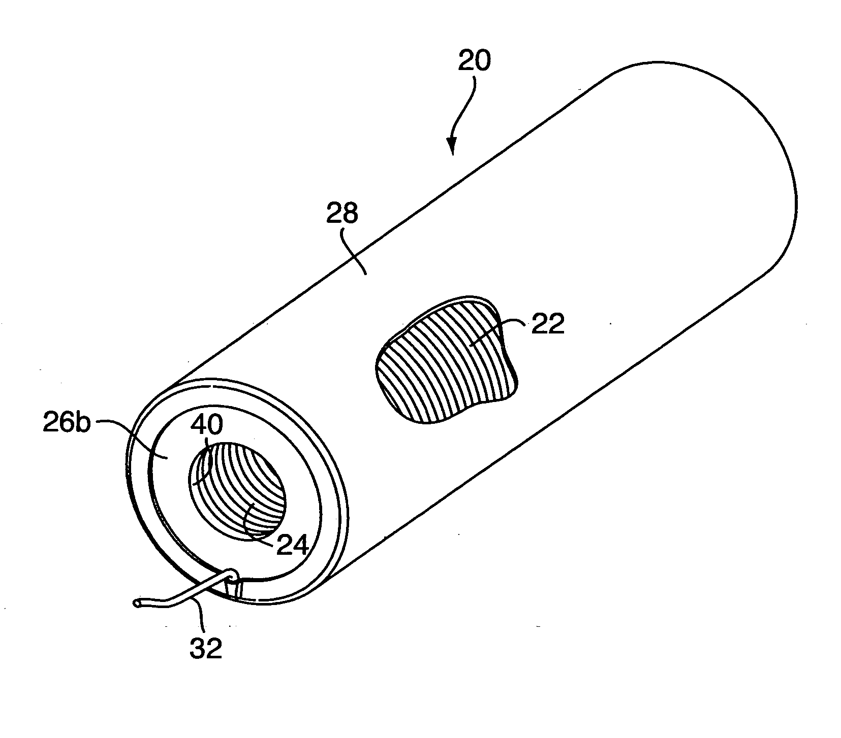
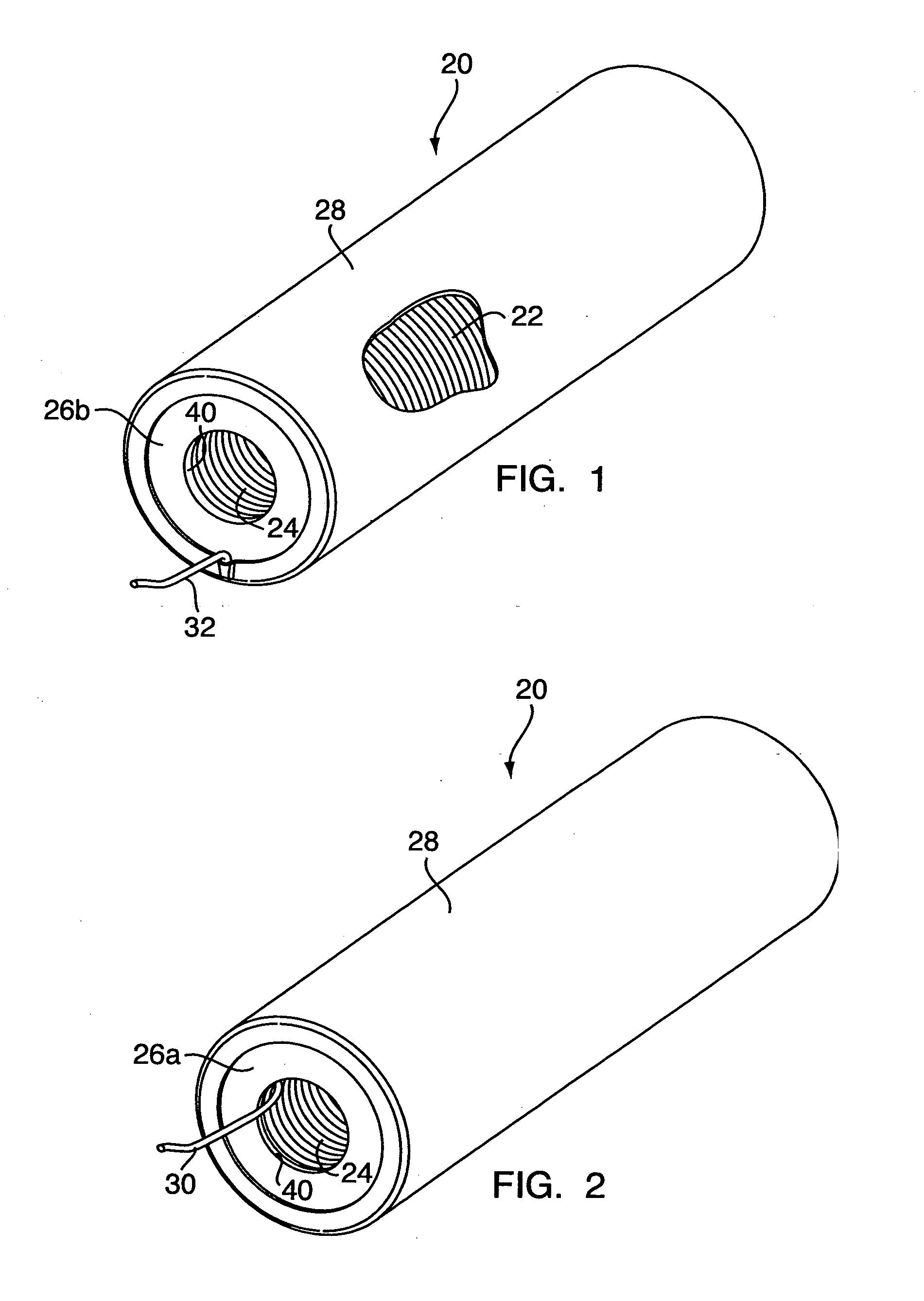
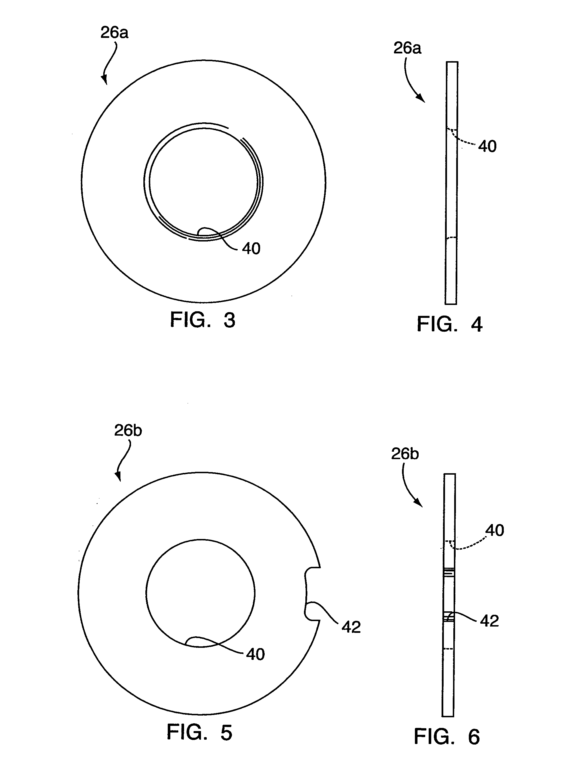
[0023] With reference to FIGS. 1-11f, an embodiment of the present invention relates to a coreless-coil shock tube package system 20, and to a method for packaging shock tubing. The package system 20 includes a “coreless” bundle of shock tubing 22, by which it is meant that the tubing bundle 22 is not supported or contained by being wrapped around a spool or other supporting structure. The tubing bundle may be a generally cylindrical (in overall shape) coil of shock tubing. Optionally, two washer-like end caps or plates 26a, 26b abut the ends of the tubing coil 22 for helping to support the coil axially. Also, a polymer, “shrink wrap” or other type outer cover or envelope 28 at least partially covers the coil 22 and end plates 26a, 26b.

[0024] Typically, one end of the tubing 22 (the “inner” end 30) is positioned at the interior 24 of the coil 22, and the other end of the tubing (the “outer” end 32) is positioned on the outside of the coil. Optionally (see FIG. 10), a detonator 34 i...


PUM


Abstract

A coreless-coil shock tube package system includes a “coreless” bundle of shock tubing, meaning that the tubing is not wrapped around a spool. The bundle may be a generally cylindrical coil of shock tubing. Optionally, two washer-like end plates abut the ends of the tubing coil for axial support. A layer of shrink-wrap or other polymer film partially covers the coil and end plates. A detonator is attached to one end of the tubing and lies tucked into the coil, through an end plate, for storage and transport. An igniter is attached to the tubing's other end. In use, the detonator is removed from the coil and attached to an explosive device. Then, the package is pulled away from the detonator and explosive, thereby uncoiling the tubing through the end plate for deployment. The igniter is actuated for igniting the shock tubing and activating the detonator and explosive.

Description

CROSS REFERENCE TO RELATED APPLICATIONS [0001] This application claims the benefit of U.S. Provisional Application Ser. No. 60 / 601,458 filed Aug. 13, 2004, herein incorporated by reference in its entirety.FIELD OF THE INVENTION [0002] The present invention relates to igniting devices and systems for explosives and, more particularly, to fuse cord and packaging for fuse cord. BACKGROUND OF THE INVENTION [0003] Shock tubes are a type of fuse cord or blasting cord used in non-electric blast initiation systems. Shock tube was originally described in U.S. Pat. No. 3,590,739 to Persson. Shock tubing typically comprises an elongated, hollow, flexible, small-diameter tube, the inner surface of which is coated with a reactive substance, e.g., a thin layer of detonating or deflagrating explosive composition. Most commonly, this composition consists of a mixture of HMX and aluminum powder. Later shock tube designs such as disclosed in U.S. Pat. No. 4,328,753 to Kristensen encompass multiple pl...

Claims


Application Information

Patent Timeline
IPC IPC(8): C06C5/06
CPCC06C5/04F42B39/00F42B39/30
Inventor BAWABE, A. JONATHAN
Owner ENSIGN BICKFORD AEROSPACE & DEFENSE
Why Eureka
Try Eureka