Driving shaft of effusion cell for deposition system and deposition system having the same

a technology of deposition system and driving shaft, which is applied in the direction of crystal growth process, polycrystalline material growth, chemically reactive gases, etc., can solve the problem of increasing the danger of collision between shelves or between shelves and other apparatus, and difficulty in confirming the position of a shelf that has been stopped and then moved,

Active Publication Date: 2006-07-06
SAMSUNG DISPLAY CO LTD
View PDF7 Cites 100 Cited by
  • Summary
  • Abstract
  • Description
  • Claims
  • Application Information

AI Technical Summary

Benefits of technology

This patent describes how to stop organic gas from sticking to the part that drives the machine used to deposit it onto other materials.

Problems solved by technology

Technical Problem: There is a problem wherein the organic vapor material can stick to the driving shaft in traditional deposition systems, leading to issues with movement of the effusion cell. Additionally, there is a risk of collisions between different parts within the deposition system due to operator errors or malfunctions. Another issue is how to accurately align a substrate and mask during stand-up alignment without inducing any warping phenomena on the final product.

Method used


Image

  • Driving shaft of effusion cell for deposition system and deposition system having the same
  • Driving shaft of effusion cell for deposition system and deposition system having the same
  • Driving shaft of effusion cell for deposition system and deposition system having the same

Examples


Embodiment Construction

[0042] The invention is described more fully hereinafter with reference to the accompanying drawings, in which embodiments of the invention are shown. This invention may, however, be embodied in many different forms and should not be construed as limited to the embodiments set forth herein. Rather, these embodiments are provided so that this disclosure is thorough, and will fully convey the scope of the invention to those skilled in the art. In the drawings, the size and relative sizes of layers and regions may be exaggerated for clarity.

[0043] It will be understood that when an element such as a layer, film, region or substrate is referred to as being “on” another element, it can be directly on the other element or intervening elements may also be present. In contrast, when an element is referred to as being “directly on” another element, there are no intervening elements present.

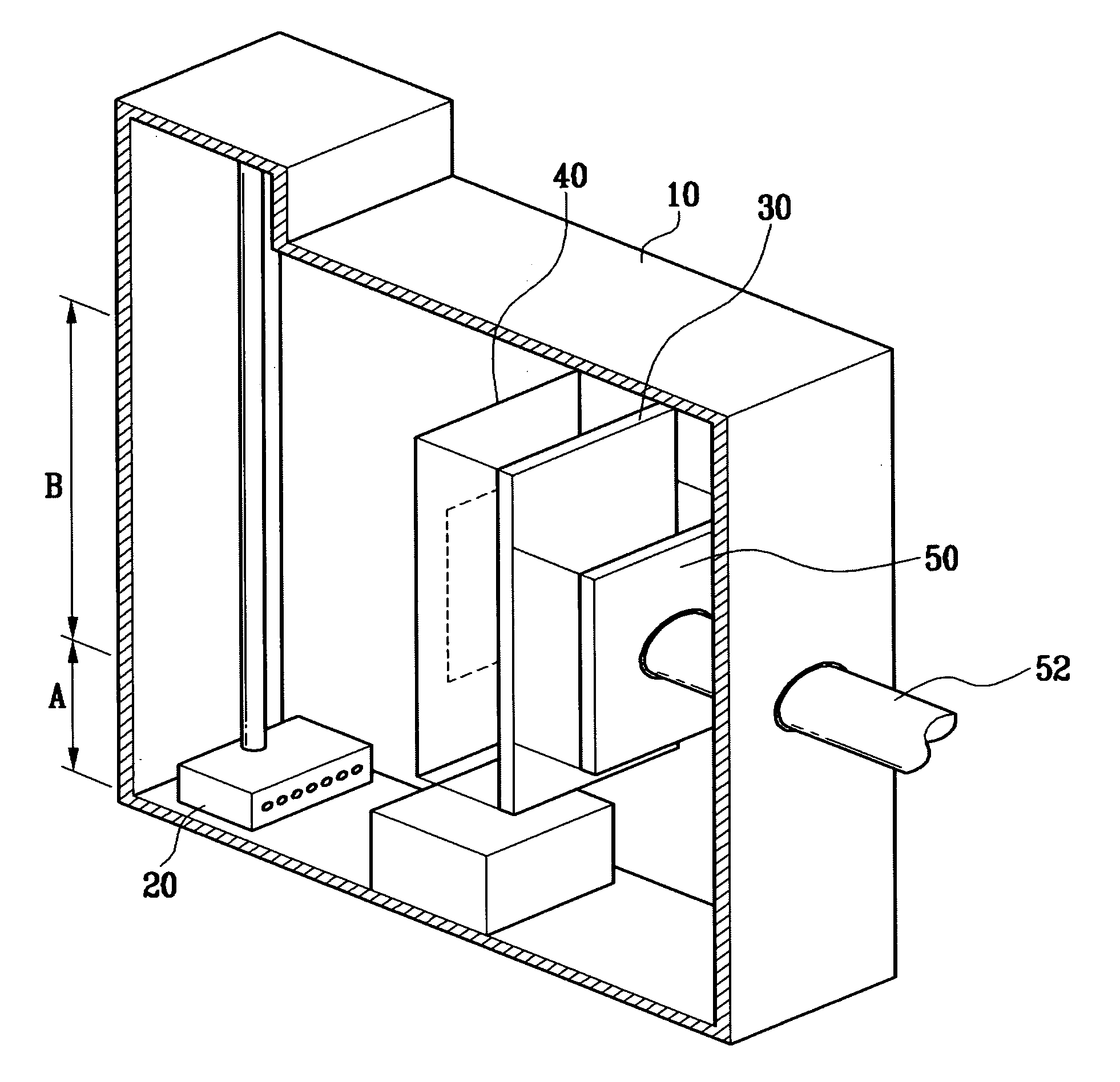
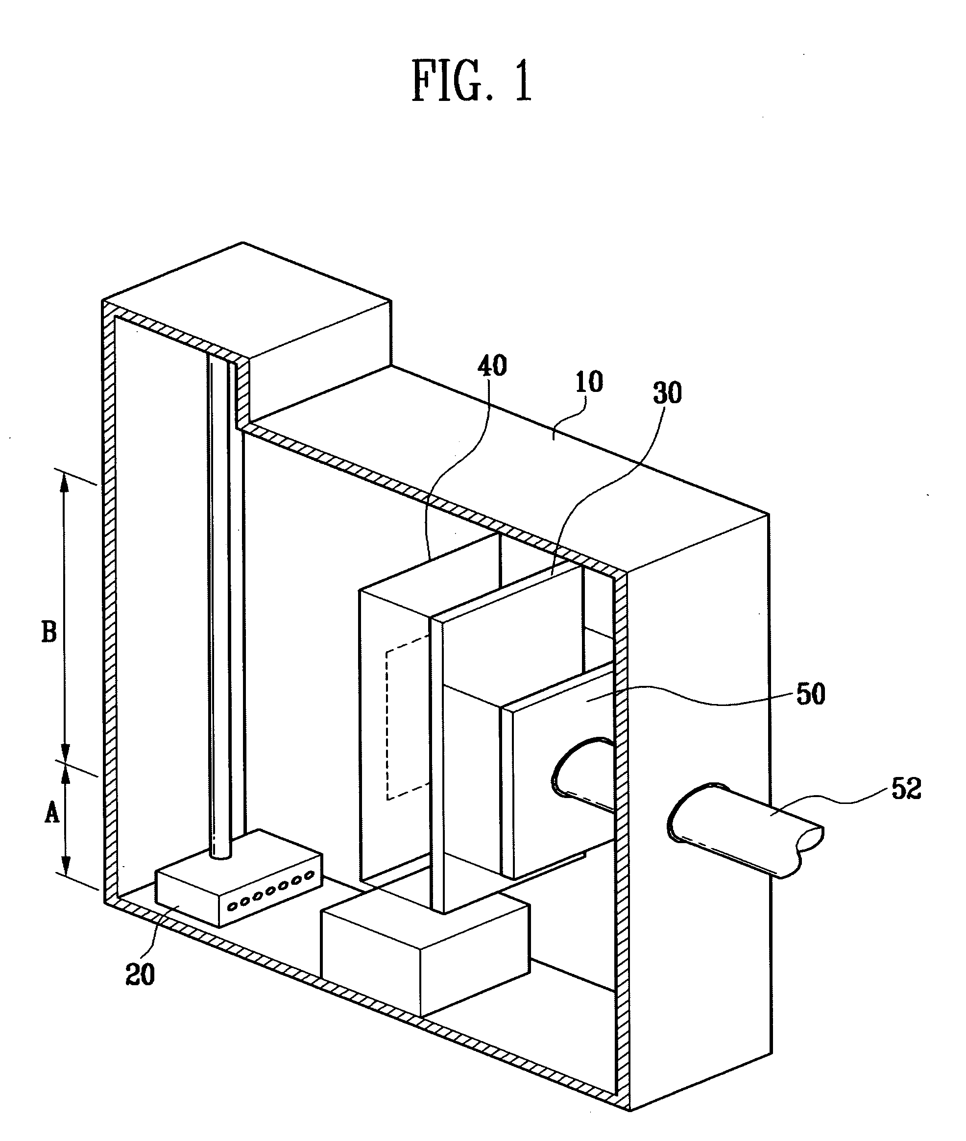
[0044]FIG. 1 is a schematic perspective view of a vacuum deposition system according to an exemplary ...


PUM

PropertyMeasurementUnit
Weightaaaaaaaaaa
Distanceaaaaaaaaaa

Abstract

Apparatus for a deposition system includes a sealing apparatus that seals the drive shaft from the deposition material to prevent the deposition material from adhering to the drive shaft, a moving apparatus to reduce the weight of a shelf on the drive shaft, and a collision-preventing apparatus that measures the distance between a shelf and an adjacent article.

Description


Claims


Application Information

Patent Timeline
Owner SAMSUNG DISPLAY CO LTD
Why Eureka
Try Eureka