
Card case, IC card, and IC card unit

Inactive Publication Date: 2006-07-06
SEIKO EPSON CORP
View PDF10 Cites 73 Cited by
  • Summary
  • Abstract
  • Description
  • Claims
  • Application Information

AI Technical Summary

Benefits of technology

[0008] An advantage of the invention is to provide a card case, an IC card, and an IC card unit that enable usage of the IC card even when the IC card is encased.
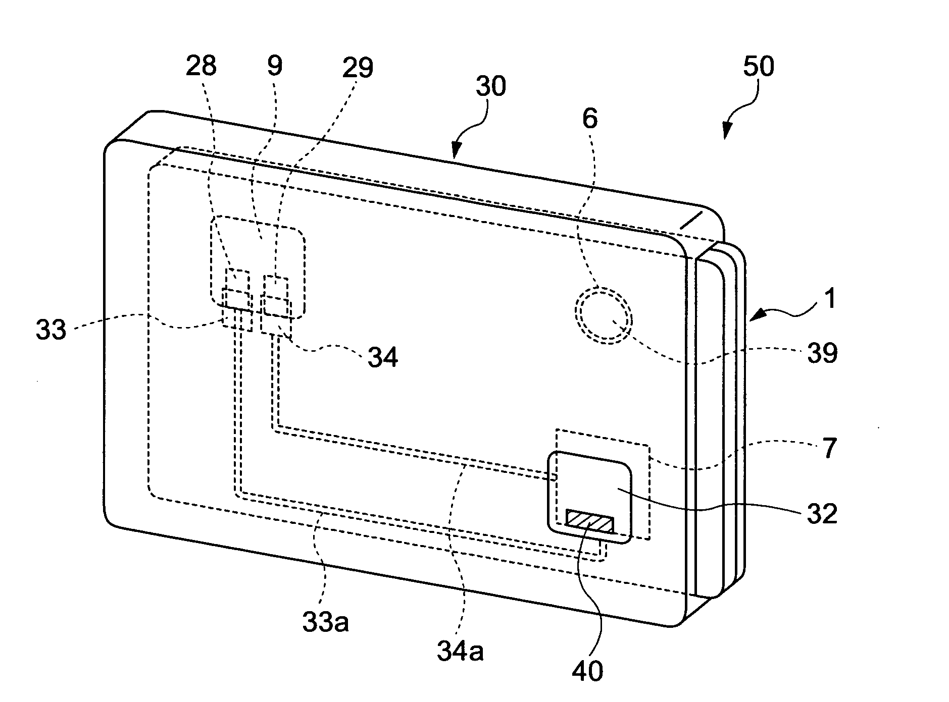
[0009] According to an aspect of the invention, a card case of the present invention, which encases an IC card having a functional section that contains a biometric information-acquiring portion for acquiring biometric information and carries out communication with an outer part of the card when the biometric information acquired at the biometric information-acquiring portion is authenticated and having a power section that supplies power to the functional section, includes: a case body that can encase the IC card and has an opening at a position two-dimensionally overlapping with the biometric information-acquiring portion so that the biometric information-acquiring portion of the encased IC card is exposed outside the case; a lid that covers the opening and is capable of opening and closing; a functional section electrode that is provided on the case body and is electrically connected to the functional section of the IC card encased in the case body; a power section electrode that is provided on the case body and is electrically connected to the power section of the IC card encased in the case body; and a connection section that electrically connects the functional section electrode with the power section electrode in a state that the lid is open.
[0010] In the invention, when the lid is opened in the state that the IC card is encased, the functional section electrode and the power section electrode are electrically connected, and the power is supplied to the functional section of the IC card. With the power supply to the functional section of the IC card, the functional section containing the biometric information-acquiring portion starts functioning. Further, when the lid is opened while the IC card is encased, the biometric information-acquiring portion is exposed outside the case, and the IC card can acquire the biometric information even from the outside of the case.
[0011] Consequently, it is possible to use the IC card even when it is encased. Even when the IC card having, for example, a switch for supplying the power to the functional section is encased, it is not necessary to take it out in order to operate the switch.
[0012] Further, it is preferable that the connection section electrically interrupts the functional section electrode from the power section electrode in a state that the lid is closed.
[0013] According to such a structure, when the lid is closed in the state that the IC card is encased, the power is not supplied to the functional section, and, therefore, it is possible to prevent the power supply when the IC card is not in use and to suppress, for example, malfunctions of the IC card. Also, since the power is supplied to the functional section only when the lid is open, electric consumption can be reduced.

Problems solved by technology

Therefore, in order to acquire the biometric information by turning on the power of the IC card in this situation, the user must go through the trouble of taking out the IC card from the card case each time.
In particular, if the user uses the IC card frequently, it is troublesome to put the IC card in and out of the card case every time he or she uses the IC card.
Further, if the user frequently puts in and out the IC card, the fingerprint authentication chip can be easily damaged.

Method used


Image

  • Card case, IC card, and IC card unit
  • Card case, IC card, and IC card unit
  • Card case, IC card, and IC card unit

Examples


Embodiment Construction

[0033] The first embodiment of the invention will now be described based on the drawings.

[0034]FIG. 1 is a plan view of a structure of an IC card unit 50 of the present embodiment. The IC card unit 50 is mainly composed of a card case 30 for encasing a card and an IC card 1 encased in this card case 30. The IC card 1 is a card that has stored the owner's personal information, such as a credit card, a cash card (an ATM card), and a company ID card, which needs to be authenticated when used.

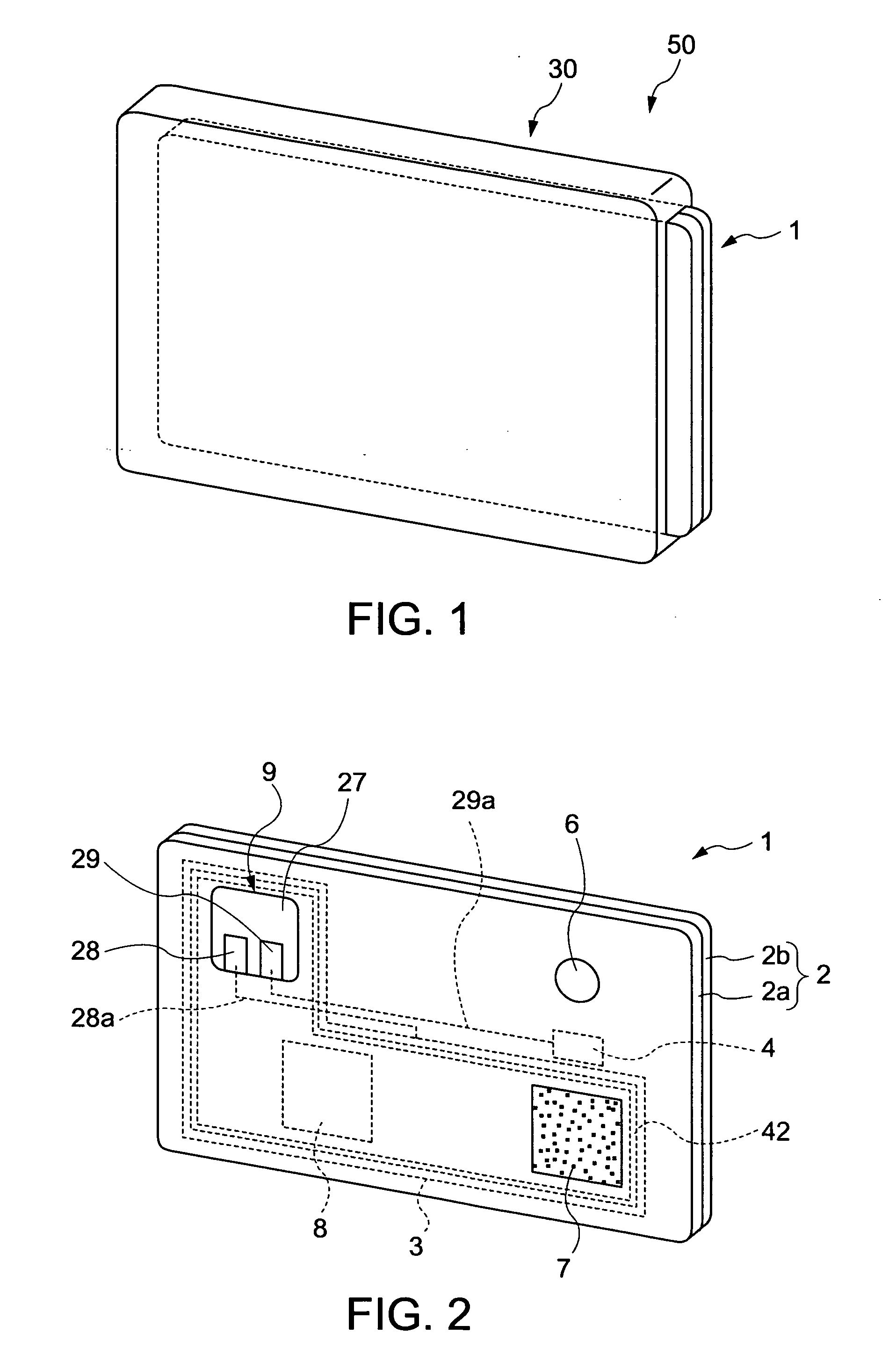
[0035]FIG. 2 is a perspective diagram showing the structure of the IC card 1.

[0036] The IC card 1 is mainly composed of a card substrate 2, a functional section 3, a power section 4, and a switch 6. The IC card 1 is about the same size as, for example, a credit card. By turning on the switch 6, power can be supplied from the power section 4 to the functional section 3. The IC card 1 is designed so that the power supplied to the functional section 3 can be switched on and off and that the power i...


PUM


Abstract

A card case, which encases an IC card having a functional section that contains a biometric information-acquiring portion for acquiring biometric information and carries out communication with an outer part of the card when the biometric information acquired at the biometric information-acquiring portion is authenticated and having a power section that supplies power to the functional section, the card case including: a case body that can encase the IC card and has an opening at a position two-dimensionally overlapping with the biometric information-acquiring portion so that the biometric information-acquiring portion of the encased IC card is exposed outside the case; a lid that covers the opening and is capable of opening and closing; a functional section electrode that is provided on the case body and is electrically connected to the functional section of the IC card encased in the case body; a power section electrode that is provided on the case body and is electrically connected to the power section of the IC card encased in the case body; and a connection section that electrically connects the functional section electrode with the power section electrode in a state that the lid is open.

Description

BACKGROUND OF THE INVENTION [0001] 1. Technical Field [0002] The present invention relates to a card case, an IC card, and an IC card unit. [0003] 2. Related Art [0004] In recent years, cards containing personal information such as an ID card and a credit card have been in use for electronic commerce and the like. In order to prevent fraudulent transactions of these cards, some cards can authenticate the card user by acquiring the user's personal information so as to confirm that the user is the right card owner. [0005] For example, an IC card using fingerprint information for the authentication has been proposed, in that: the fingerprint information of an individual is read out; a fingerprint authentication chip that determines authenticity of the read out fingerprint is mounted on the IC card; and by determining whether the fingerprint authentication information stored inside the chip matches with the read out fingerprint information, the individual's authentication is conducted (...

Claims


Application Information

Patent Timeline
IPC IPC(8): G06K19/06G06K7/00
CPCG06K19/005G06K19/07345G06K19/077
Inventor TAKAO, HIROKI
Owner SEIKO EPSON CORP
Learn More