Method and a digital-to-analog converter for converting a time varying digital input signal

a digital input signal and converter technology, applied in digital-analog converters, transmission systems, instruments, etc., can solve the problems of limited degree to which the sampling rate and the resolution of a dac can be increased, and achieve the reduction of waveform errors in the analogue voltage output signal, the resolution of the current steering dac is not increased, and the resolution of the current steering dac is reduced.

Active Publication Date: 2006-07-06
ANALOG DEVICES INC
View PDF5 Cites 35 Cited by
  • Summary
  • Abstract
  • Description
  • Claims
  • Application Information

AI Technical Summary

Benefits of technology

[0089] The advantages of the DAC according to the invention are many. The current steering DAC according to the invention provides a reconstructed analogue voltage output signal which is reconstructed from the data samples with substantially infinite resolution, and without oversampling and with no increase in the resolution of the current steering DAC being required. This is achieved by virtue of the fact that the reconstructed analogue voltage output signal is reconstructed with continuous linear interpolation. By sequentially determining difference values between the data samples, and sequentially converting the difference values to corresponding proportional current signals, which are proportional to the difference values, and by sequentially steering the proportional current signals to the predominantly capacitive load impedance for the duration of the time period between the data samples, the difference value of which is determined, the proportional current signals are integrated with respect to time during each time period, thereby producing a continuously linearly interpolated reconstructed analogue voltage output signal.
[0090] Accordingly, by appropriately configuring the transfer function of the DAC, to provide positive flowing proportional current signals corresponding to positive difference values, and negative flowing proportional current signals corresponding to negative difference values, each positive difference value results in a linear increase, with respect to time, in the voltage developed across the predominantly capacitive load impedance during the time period, during which the proportional current is steered to the predominantly capacitive load impedance, and vice versa in the case of a negative flowing proportional current signal, which results in a linear decrease, with respect to time in the voltage developed across the predominantly capacitive load impedance. Thus, the analogue voltage output signal is reconstructed with continuous linear interpolation, and thus is provided with substantially infinite resolution.
[0091] In cases where the DAC is configured with a transfer function which provides negative flowing proportional current signals in response to positive difference values, and vice versa in respect of negative difference values, the reconstructed analogue voltage output signal is an inversion of the original signal from which the data samples had been derived. However, in such cases the analogue voltage output signal is still constructed with continuous linear interpolation, and thus, is provided with substantially infinite resolution.
[0092] Each difference value may be determined between the current data sample and any prior data sample. For example, the difference values may be determined between every second data sample or every third data sample, or indeed, between every fourth or more data samples. However, the closer the data samples, between which the difference values are determined, are to each other, the more accurate will be the reconstructed analogue voltage output signal. The most accurate analogue voltage output signal is reconstructed when difference values are determined between consecutive ones of the data samples, and these difference values are converted into proportional current signals, which are sequentially steered to the predominantly capacitive load impedance.
[0093] By virtue of the fact that the reconstructed analogue voltage output signal is provided with continuous linear interpolation, and thus is provided with substantially infinite resolution, waveform errors in the analogue voltage output signal are minimised.
[0094] Similar advantages are provided by the method according to the invention for converting the time varying digital input signal to the analogue voltage output signal, and similar advantages are also achieved by the method according to the invention for operating a current steering DAC for converting a time varying digital input signal to an analogue voltage output signal.

Problems solved by technology

The degree to which the sampling rate and the resolution of a DAC can be increased is limited by various parameters, for example, technological limits, power requirement, silicon area and, in general, cost considerations.
This is undesirable, and there is therefore a need for a frequency synthesiser which addresses this problem.

Method used


Image

  • Method and a digital-to-analog converter for converting a time varying digital input signal
  • Method and a digital-to-analog converter for converting a time varying digital input signal
  • Method and a digital-to-analog converter for converting a time varying digital input signal

Examples


Embodiment Construction

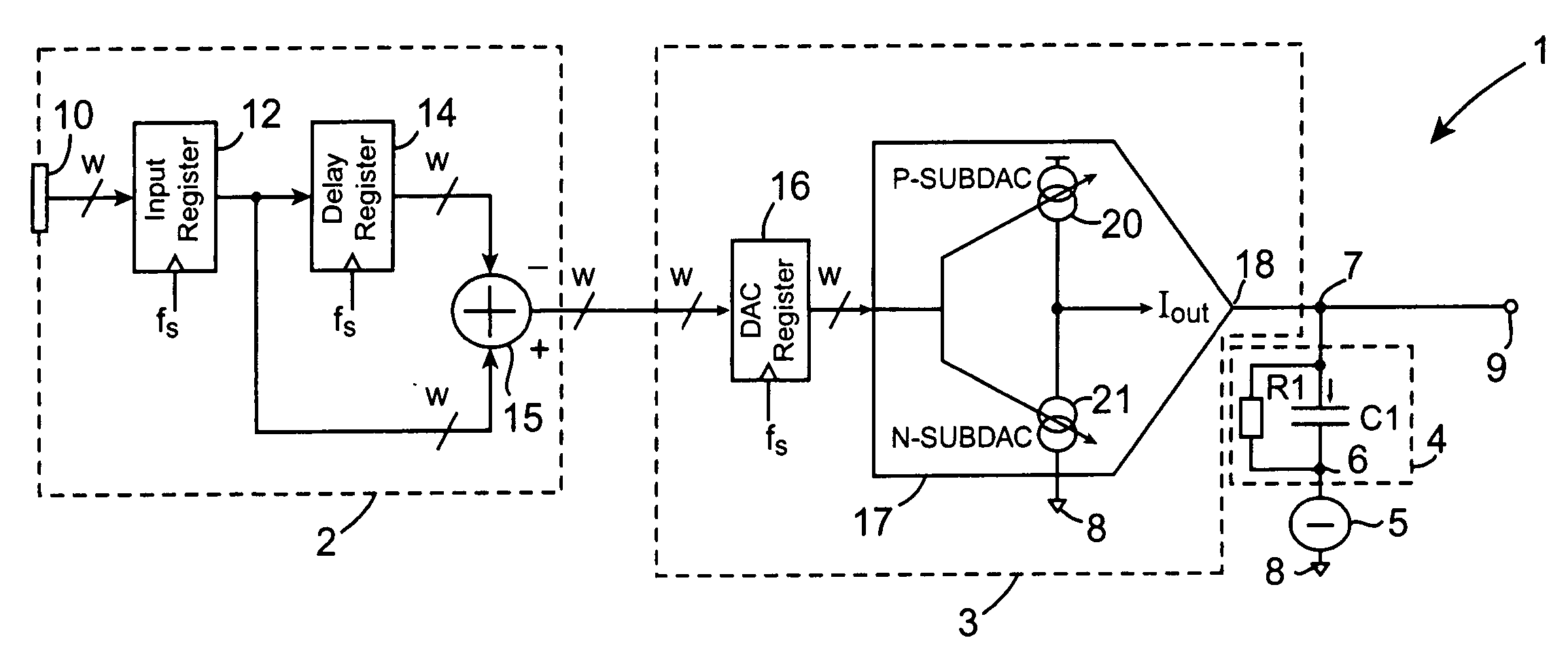
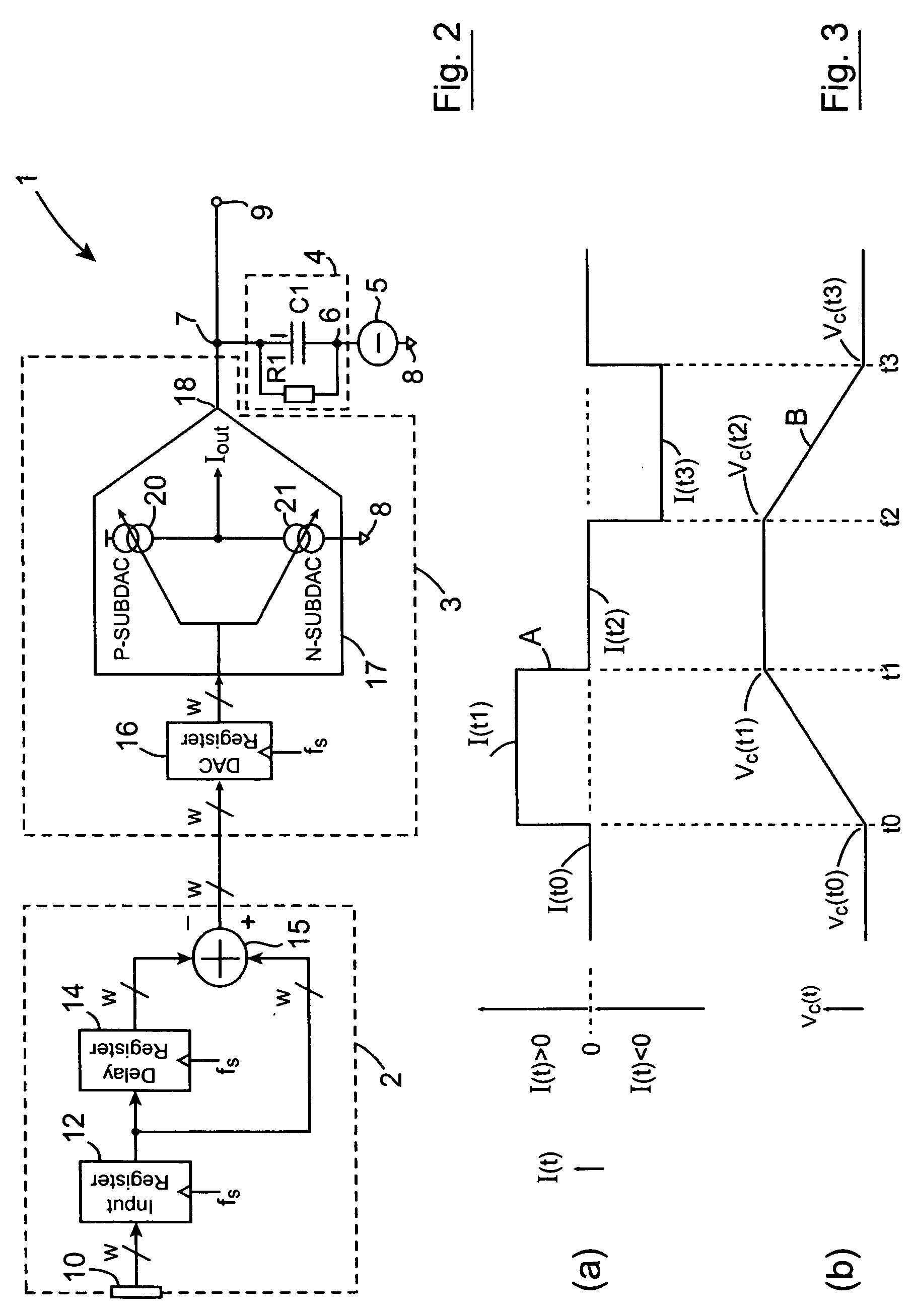
[0114] Referring to the drawings and initially to FIG. 2, there is illustrated a digital-to-analogue converter (DAC) according to the invention, indicated generally by the reference numeral 1, for converting a time varying digital input signal comprising consecutive data samples provided to the DAC 1 at a data sampling rate fs into a reconstructed continuously linearly interpolated analogue voltage output signal of substantially infinite resolution. The DAC 1 comprises a digital signal processing circuit 2 for receiving the data samples at the data sampling rate fs, and for sequentially determining difference values between consecutive data samples of the digital input signal on respective clock cycles of the data sampling rate fs. A current steering DAC circuit 3 sequentially converts the difference values determined by the digital signal processing circuit 2 into corresponding proportional analogue current signals, the values of which are proportional to the respective correspondi...


PUM


Abstract

A digital-to-analogue converter (DAC) (1) comprises a digital processing circuit (2) having an input register (10) to which data samples of a digital input signal are written at a data sampling rate (fs). A delay register (14) holds each data sample for one clock cycle of the data sampling rate (fs), and a subtracting circuit (15) sequentially produces difference values between consecutive ones of the data samples by subtracting the data sample in the delay register (14) from the input register (12) on each clock cycle of the data sampling rate (fs). The difference values are sequentially converted to proportional analogue current signals by a current steering DAC circuit (3) which sequentially steers the proportional current signals for the duration of the respective clock cycles of the data sampling rate (fs) to a predominantly capacitive load impedance (4), which is coupled to ground 8 through a voltage reference source (5) and the voltage developed across the predominantly capacitive load impedance (4) with respect to ground (8) is a continuously linearly interpolated analogue voltage representative of the data sample of the digital input signal.

Description

[0001] Priority under 35 U.S.C., Section 119(e) is hereby claimed to U.S. Provisional Application Ser. No. 60 / 628,716, filed on Nov. 17, 2004 entitled “A METHOD AND A DIGITAL-TO-ANALOGUE CONVERTER FOR CONVERTING A TIME VARYING DIGITAL INPUT SIGNAL TO A CONTINUOUSLY LINEARLY INTERPOLATED ANALOGUE VOLTAGE OUTPUT SIGNAL AND A FREQUENCY SYNTHESISER FOR SYNTHESISING A SIGNAL WITH JITTER MINIMISED”.FIELD OF THE INVENTION [0002] The present invention relates to a method for converting a time varying digital input signal comprising consecutive data samples at a data sampling rate to a continuously linearly interpolated analogue voltage output signal with substantially infinite resolution. The invention also relates to a digital-to-analogue converter (DAC) and a method for operating a current steering DAC for converting a time varying digital input signal comprising consecutive data samples at a data sampling rate to a continuously linearly interpolated analogue voltage output signal with su...

Claims


Application Information

Patent Timeline
Patent Type & Authority Applications(United States)
IPC IPC(8): H03M1/66
CPCH03M1/66
Inventor TUCHOLSKI, HANS
Owner ANALOG DEVICES INC
Why Eureka
Try Eureka