Computer assisted manipulation of catheters and guide wires

a technology of guide wires and catheters, applied in the field of computer assisted manipulation of catheters and guide wires, can solve the problems of reducing ventilation, significant exposure to radiation, and reducing the ventilation effect of catheters

Inactive Publication Date: 2006-07-06
SCHNEIDER M BRET
View PDF19 Cites 98 Cited by
  • Summary
  • Abstract
  • Description
  • Claims
  • Application Information

AI Technical Summary

Benefits of technology

[0017] Advantages of the invention can include the ability to manipulate minimally invasive surgical tools while under fluoroscopic visualization by remote control, virtually eliminating radiation exposure and permitting, if desired, the operating physician and the patient being separated by great geographical distances. Other advantages of the invention can include that fewer individuals may be required to manipulate the elongate members, the elongate members may be manipulated in a more efficient manner (e.g., to the desired destination) and elongate members can be exchanged without affecting the position of the other elongate members.
[0025] In another embodiment, the entire invention has a linear configuration (no drum) and uses clamshell designs so that catheter or wire devices do not have to be threaded through rings or tubes.

Problems solved by technology

A major drawback to the use of elongate members in the minimally invasive surgical environment from the perspective of the physician is significant exposure to radiation due to the fluoroscopic cameras used to visualize the path and tip of guide wires, guide catheters, balloon catheters, biopsy needles, and other minimally invasive instruments.
However, the use of such garments itself presents an occupational hazard due to the wear and tear inflicted on the user's body, secondary to the weight and stiffness, and reduced ventilation that characterize such wearable radiation shields.
Additionally, the arms and head of the user are not typically covered by such garments, making radiation shield at best incomplete.
Another disadvantage is that the elongate members are quite long and difficult to manually manipulate.
Additionally, it can be very difficult to manually maneuver the elongate members to their desired destination, manipulating a precise portion of the device to an exactly targeted spot within the body.
This difficulty can be compounded by the complication that when a physician retracts one of the elongate members, such as to use a different elongate member, the other elongate members may be accidentally drawn from their desired location.

Method used


Image

  • Computer assisted manipulation of catheters and guide wires
  • Computer assisted manipulation of catheters and guide wires
  • Computer assisted manipulation of catheters and guide wires

Examples


Embodiment Construction

[0059] In the description that follows, the present invention will be described in reference to embodiments that utilize computers and electromechanical devices to manipulate elongate members such as catheters and guide wires. More specifically, the embodiments will be described in reference to preferred embodiments. However, embodiments of the invention are limited to any particular configuration, architecture, or specific implementation. Therefore, the description of the embodiments that follows is for purposes of illustration and not limitation.

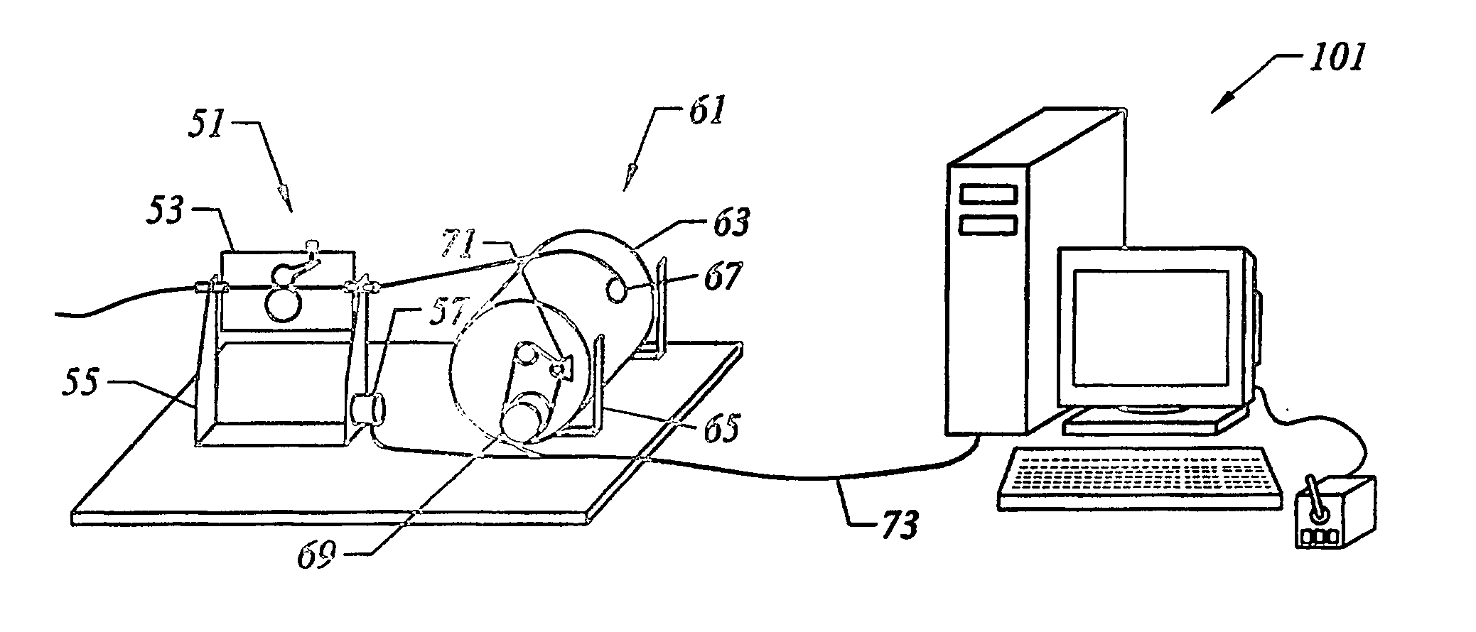
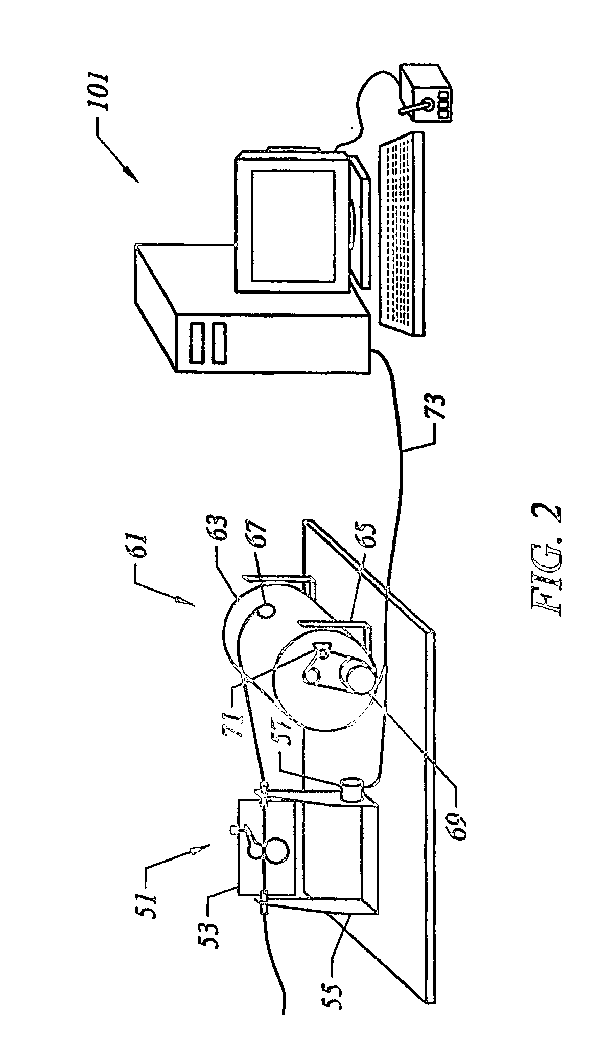
[0060]FIG. 2 shows a system of one embodiment of the invention that provides computer-assisted manipulation of elongate members in medical procedures. A module base assembly 51 is proximal to the patient and allows for advancement, retraction, rotation, and retention of elongate members. Module base assembly 51 includes a module base 53 that is supported by a stand 55.

[0061] Module base 53 may be rotated along the axis of the elongate me...


PUM


Abstract

Computer-assisted methods and systems for manipulating elongate members during medical procedures are provided. Electromechanical devices are computer driven to manipulate the elongate members, which a user can direct through computer interfaces like graphical user interfaces and pointing devices.

Description

BACKGROUND OF THE INVENTION [0001] The present invention relates to computer-assisted manipulation of elongate (flexible or rigid) members while performing medical procedures or surgery. More specifically, the invention relates to computer-assisted manipulation of catheters and guide wires during medical procedures. [0002] There are numerous kinds of minimally surgical procedures that require the manipulation of elongated elongate members through areas of a patient's body. A common example is angioplasty that attempts to increase blood through a blocked artery. The elongated elongate members can include guide catheters, interventional catheters (e.g., angioplasty or stent), guide wires, and the like. Typically, such procedures are performed by physicians who are in the fields of cardiology, radiology, and neurosurgery. [0003]FIG. 1 shows an illustration of a common medical procedure such as angioplasty. An incision is made to reach a large artery, such as incision 1 in the femoral a...

Claims


Application Information

Patent Timeline
Patent Type & Authority Applications(United States)
IPC IPC(8): G09G5/00A61BA61F11/00A61M25/01
CPCA61M25/0105A61M25/0113
Inventor SCHNEIDER, M. BRET
Owner SCHNEIDER M BRET
Why Eureka
Try Eureka