Optical disc and physical address format

a physical address and optical disc technology, applied in the field of optical disc media, can solve the problems of unfavorable recording, inability to detect/correct digital signals,

Inactive Publication Date: 2006-07-06
PANASONIC CORP
View PDF1 Cites 10 Cited by
  • Summary
  • Abstract
  • Description
  • Claims
  • Application Information

AI Technical Summary

Problems solved by technology

In consideration of the higher density recording which will be required in the future, all the above-mentioned structures have their own problems.
Thus, the memory capacity is inevitably reduced by the space for the addresses.
Then, it may undesirably occur that the PLL cannot sufficiently follow disc motor jitters or jitters generated by, for example, de-centering of the disc.
This results in jitters remaining in a recording signal.
As a result, the noise component is mixed in with a wobble reproduction signal and thus further increases the jitters.
Thus, it is difficult to provide a sufficient number of pre-pits each having a sufficient length.
Therefore, there is an undesirable possibility that the number of detection errors is increased especially when the recording density is significantly high.

Method used


Image

  • Optical disc and physical address format
  • Optical disc and physical address format
  • Optical disc and physical address format

Examples


example 1

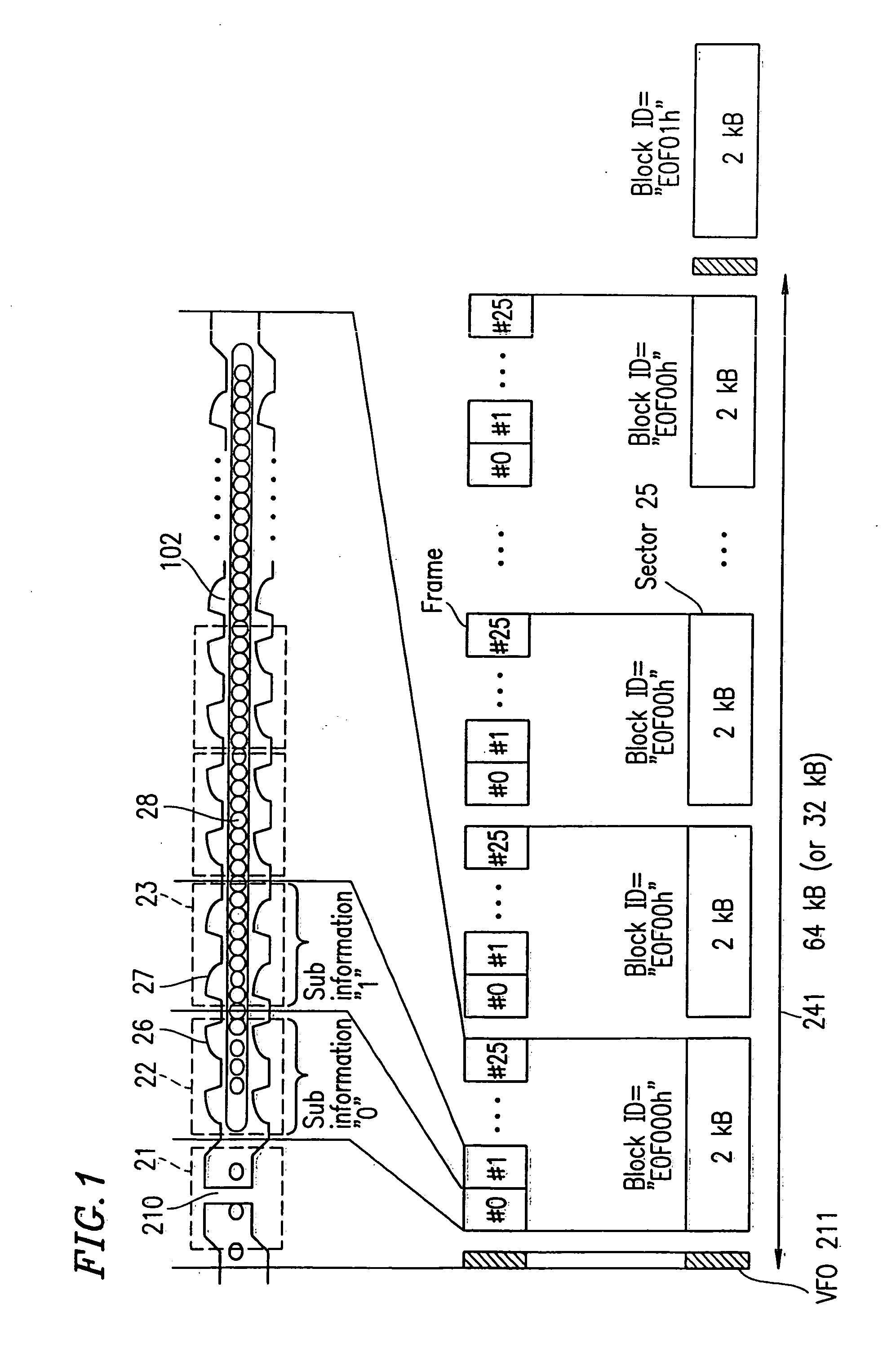
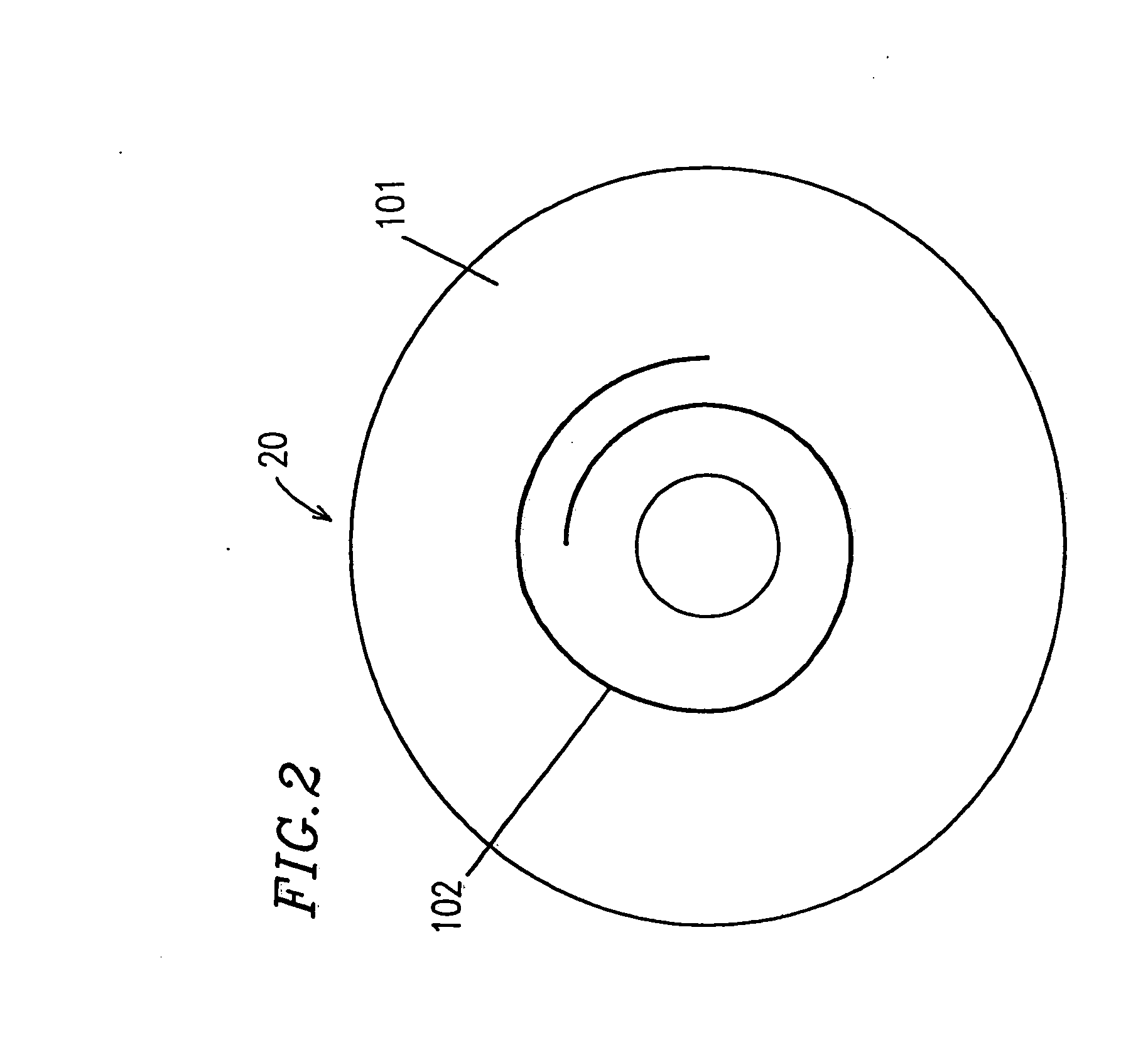
[0092]FIG. 2 shows an optical disc medium 20 according to Example 1 of the present invention. The optical disc medium 20 has a recording face 101, which has a spiral track groove 102 formed therein. As shown in FIG. 1, the track groove 102 has shapes which are different on a block-by-block basis. In FIG. 1, a block mark (identification mark) 210 is a cut-off portion in the track groove 102 and shows an index indicating a leading end of each block.

[0093] Each block is divided into N number of sectors 25 (N=32 or 16), and each sector 25 (sub block) is divided into M number of frames #0 through #25 (M=26). Each frame (fundamental unit) has a prescribed number of wobbles 26 or 27 in a periodical manner. The wobbles 26 and 27 have different prescribed shapes from each other, and represent sub information (“0”, “1” or “S”). One type of sub information (“0”, “1” or “S”) is represented by one shape of wobbles 26 or 27. The type of sub information and the shape of wobbles (wobbles 26 or 27)...

example 2

[0113]FIG. 3 shows a track groove 10 according to Example 2 of the present invention. The track groove 10 can be formed in the optical disc medium 20 shown in FIG. 2 instead of the track groove 102 shown in FIG. 1. In this example, the track groove 10 has wobbles 28 indicating sub information “S” recorded in a frame 24 in addition to the wobbles 26 in the frame 22 indicating the sub information “0” and wobbles 27 in the frame 23 indicating the sub information “1”. As in Example 1, address information is represented by a combination of sub information “0” and sub information “1”. The sub information “S” is provided at a leading end of the block, and used for indicating the leading end of the block instead of the block mark 210 shown in FIG. 1. In this way, the overhead required for the block mark 210 can be eliminated. In this example, the wobbles 28 representing the sub information “S” have a steep rising gradient and a steep falling gradient.

example 3

[0114]FIG. 4 shows a track groove 11 according to Example 3 of the present invention. The track groove 11 can be formed in the optical disc medium 20 shown in FIG. 2 instead of the track groove 102, shown in FIG. 1. In the first and second examples, one shape of wobbles is repeated periodically in correspondence with one type of sub information, and wobbles having different rising gradients and different falling gradients are used for different types of sub information. In this example, wobbles 29 and 30 are formed so as to have different duty ratios in accordance with the type of sub information. More specifically, as shown in FIG. 4, the wobbles 29 indicating sub information “0” recorded in a frame 32 is wider in one of a ridge or a trough (in the trough in the example of FIG. 4), and the wobbles 30 indicating sub information “1” recorded in a frame 34 is wider in the other of the ridge or the trough (in the ridge in the example of FIG. 4). Such a feature eliminates the necessity ...


PUM

PropertyMeasurementUnit
radiusaaaaaaaaaa
radiusaaaaaaaaaa
radiusaaaaaaaaaa

Abstract

An optical disc medium compares a track groove, along which main information is recorded. The track groove is divided into a plurality of blocks. The plurality of blocks each include a plurality of frames. The plurality of frames each include one shape of wobbles indicating sub information, among a plurality of prescribed shapes of wobbles. The plurality of blocks each have address information. The address information is represented by a string of at least one piece of sub information represented by the shape of wobbles of at least one of the plurality of frames.

Description

[0001] This application is a continuation of U.S. patent application Ser. No. 10 / 111,823, filed on Apr. 26, 2002, which is hereby incorporated herein by reference in its entirety.TECHNICAL FIELD [0002] The present invention relates to an optical disc medium for recording information (for example, digital video information) at a high density, and an optical disc apparatus and an optical disc reproduction method used for the optical disc medium. BACKGROUND ART [0003] Recently, the recording density of the optical disc media has become increasingly higher. In general, a recordable optical disc medium has track grooves therein in advance, and information is recorded along the track grooves, i.e., on the track grooves or an area interposed between the track grooves (referred to as a “land”). The track grooves are sine-like wobbles, and the information is recorded in synchronization with clocks generated based on the period of the wobbles. Addresses are provided along the track groove in ...

Claims


Application Information

Patent Timeline
Patent Type & Authority Applications(United States)
IPC IPC(8): G11B7/00G11B5/09G11B7/007G11B7/24082G11B7/24091G11B20/12G11B27/19G11B27/24G11B27/30
CPCG11B7/0053G11B7/24082G11B20/00601G11B20/10G11B20/12G11B20/1217G11B20/1833G11B27/19G11B27/24G11B27/3027G11B2020/1222G11B2020/1232G11B2020/1239G11B2020/1268G11B2020/1298G11B2220/20G11B2220/235G11B2220/2537G11B7/007
Inventor NAKAMURA, ATSUSHIMINAMINO, JUNICHIFURUMIYA, SHIGERUSHOJI, MAMORUISHIDA, TAKASHIISHIBASHI, HIROMICHI
Owner PANASONIC CORP
Why Eureka
Try Eureka