
Mobile terminal device and hand-off method thereof

a mobile terminal and hand-off technology, applied in multiplex communication, data switching networks, wireless commuication services, etc., can solve the problems of not being able to support such roaming capabilities, unable to deliver packets to mobile nodes, and adding to the processing load of base stations

Active Publication Date: 2006-07-06
PANASONIC INTELLECTUAL PROPERTY CORP OF AMERICA
View PDF17 Cites 76 Cited by
  • Summary
  • Abstract
  • Description
  • Claims
  • Application Information

AI Technical Summary

Benefits of technology

[0007] It is an object of the present invention to provide a mobile terminal apparatus and handoff method thereof which are capable of achieving smooth, continuous communications sessions even when in transit, regardless of base station capabilities and functionalities, in a packet-switched data communications network.

Problems solved by technology

In a packet-switched communications network, however, supporting such roaming capabilities is difficult.
However, there exist a time when the mobile node has left a previous point of attachment and yet to set up a new binding between its home-address and new care-of-address (or even have not yet received a new care-of-address).
During this time, no packet can be delivered to the mobile node.
In the above-described conventional method, however, the fast handoff requires base stations to actively participate, adding burden to the base stations' processing loads.
This makes the deployment of such method more complex, and often more expensive.
Existing solutions such as the above-described conventional method for supporting mobility in a packet-switched data communications network is inadequate in ensuring that a mobile terminal has a smooth, continuous communications session when in transit, because, although the method enables fast handoff between base stations, it still requires additions to base station functionalities.
Not only does this increase the processing burden of the base station, it also requires special efforts to ensure compatibility between base stations from different vendors and service providers.

Method used


Image

  • Mobile terminal device and hand-off method thereof
  • Mobile terminal device and hand-off method thereof
  • Mobile terminal device and hand-off method thereof

Examples


embodiment 1

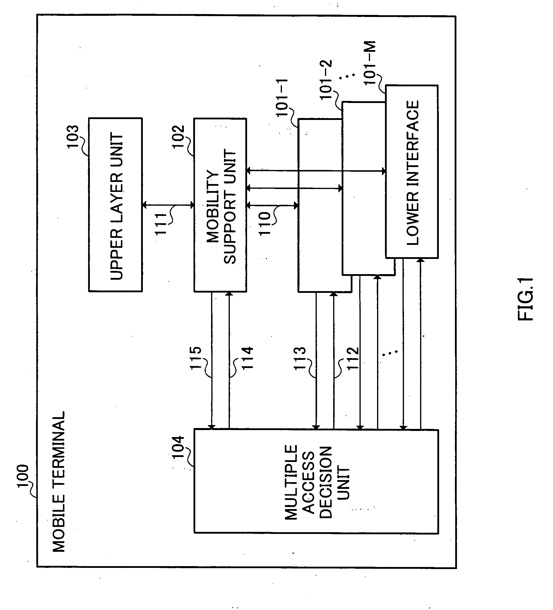
[0032]FIG. 1 is a block diagram showing the architecture of a mobile terminal according to Embodiment 1 of the present invention. Mobile terminal 100 shown in FIG. 1 has M number (M is an integer greater than or equal to 2) of lower interfaces 101-1 to 101-M, mobility support unit (MSU) 102, upper layer unit 103, and multiple access decision unit (MADU) 104. When reference is made to any one or more of lower interfaces 101-1 to 101-M, the lower interface(s) will be hereinafter referred to as “lower interface 101.”

[0033] The different access mechanisms available in the mobile terminal are abstracted into lower interfaces 101-1 to 101-M. Lower interface 101 is a collective block to refer to: physical network interface hardware; software controlling the hardware; and protocols that govern the communications through such hardware. For example, under the International Organization for Standardization's (ISO) open systems interconnection (OSI) model, lower interface 101 will include all p...

embodiment 2

[0058]FIG. 4 is a block diagram showing the architecture of a mobile terminal according to Embodiment 2 of the present invention. Mobile terminal 200 shown in FIG. 4 has a basic architecture similar to that of the mobile terminal explained in Embodiment 1, and therefore the elements of mobile terminal 200 that are identical to those of mobile terminal 100 will be given identical reference numerals, and detailed description thereof will be omitted.

[0059] Mobile terminal 200 has M number of lower interfaces 201-1 to 201-M and MADU 202 instead of lower interfaces 101-1 to 101-M and MADU 104 of mobile terminal 100. Hereinafter, when reference is made to any one or more of lower interfaces 201-1 to 201-M, the lower interface(s) will be referred to as “lower interface 201.”

[0060] As a technical feature explained in the present embodiment, in mobile terminal 200, lower interface 201 uses prediction techniques to indicate to MADU 202 that it may go down in a short period of time. Therefore...

embodiment 3

[0083]FIG. 7 is a block diagram showing the architecture of a mobile terminal according to Embodiment 3 of the present invention. Mobile terminal 300 shown in FIG. 7 has a basic architecture similar to that of mobile terminal explained in Embodiment 1, and therefore the elements of mobile terminal 300 that are identical to those of mobile terminal 100 will be given identical reference numerals, and detailed description thereof will be omitted.

[0084] Mobile terminal 300 has M number of lower interfaces 301-1 to 301-M and MADU 302 instead of lower interfaces 101-1 to 101-M and MADU 104 of mobile terminal 100. Hereinafter, when reference is made to one or more of lower interfaces 301-1 to 301-M, the lower interface(s) will be referred to as “lower interface 301.”

[0085] The above-described embodiments disclosed methods whereby mobile terminals 100 and 200 can achieve seamless hand off with a plurality of active access links. In addition, in the present embodiment, it can be extended so...


PUM


Abstract

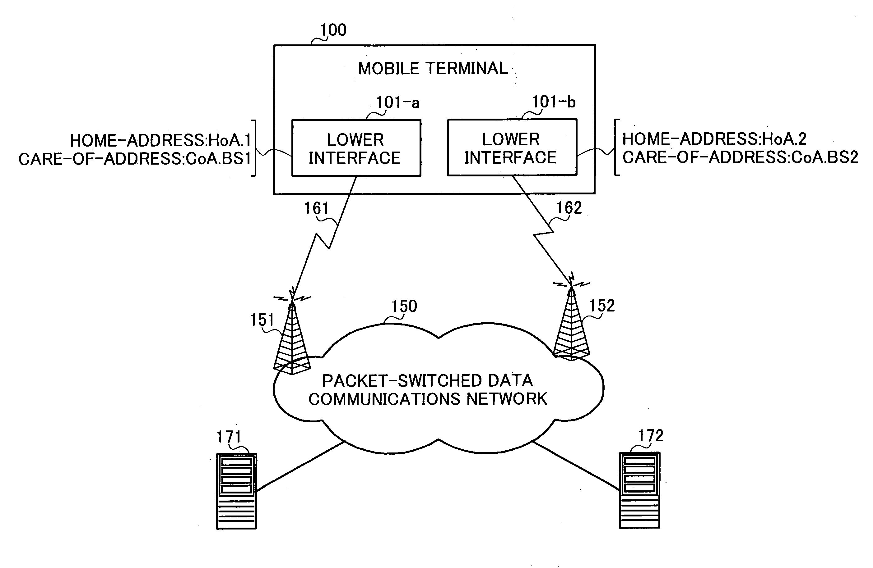
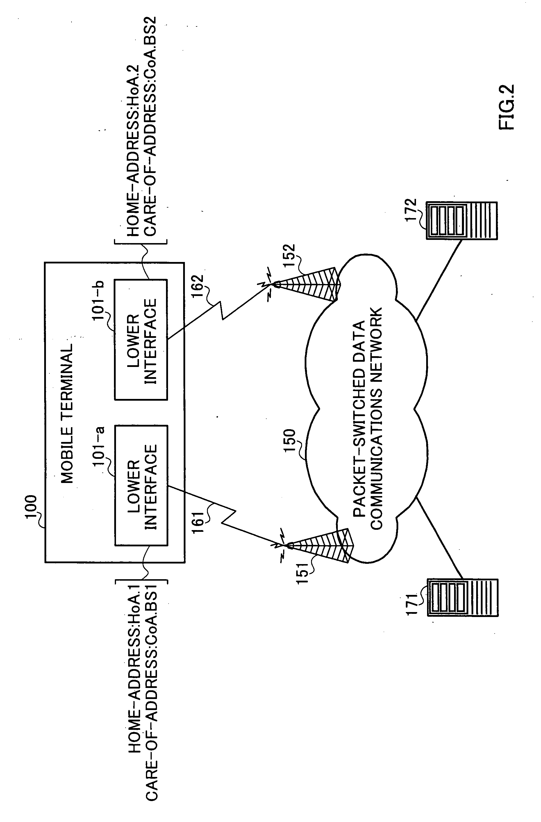
A mobile terminal that ensures smooth, continuous communications sessions even when in transit, regardless of base station capabilities and functionalities, in a packet-switched data communications network. With this terminal, each of a plurality of lower interfaces 101-1 to 101-M, when its associated access mechanism is in an active state, can obtain a connection to packet-switched data communications network 150 using its home-address HoA.1 or its care-of-address CoA.BS1. When lower interface 101-a loses its connection obtained using the care-of-address CoA.BS1, multiple access decision unit 104 instructs mobility support unit 102 to set up a binding of the home-address HoA.1 and either one of the home-address HoA.2 and the care-of-address CoA.BS2 of another lower interface 101-b. Mobility support unit 102 sets up the binding according to the instruction from multiple access decision unit 104.

Description

TECHNICAL FIELD [0001] The present invention relates to a mobile terminal apparatus and a handoff method thereof, and in particular to a mobile terminal apparatus which has a plurality of access mechanisms to a packet-switched data communications network and constantly changes its point of attachment to the packet-switched data communications network. BACKGROUND ART [0002] With the emergence and proliferation of wireless technology, the Internet today has evolved to a stage where numerous data communications end-points are made up of mobile terminals, each roaming through different domains and attaching itself to different points of attachment to a packet-switched data communications network (such as, the Internet) at different points in time. Such roaming provisioning is fairly matured in a circuit-switched communications network, such as the phone system. In a packet-switched communications network, however, supporting such roaming capabilities is difficult. This is because mobile...

Claims


Application Information

Patent Timeline
Patent Type & Authority Applications(United States)
IPC IPC(8): H04Q7/00H04J3/24H04L12/28G06FH04L29/06H04W36/08H04W36/36H04W60/00H04W80/04H04W84/12H04W88/06H04W88/08
CPCH04L12/5692H04W36/0016H04W36/0027H04W36/08H04W60/005H04W80/04H04W88/06H04W12/06H04W48/20
Inventor NG, CHAN WAHTAN, PEK YEW
Owner PANASONIC INTELLECTUAL PROPERTY CORP OF AMERICA
Learn More