Overmolded multi-port optical connection terminal having means for accommodating excess fiber length

a multi-port, optical connection technology, applied in the direction of optical light guides, fibre mechanical structures, instruments, etc., can solve the problems of difficult access to the splice closure, difficult reconfiguration of the splice closure, and time-consuming process of entering the splice closure, so as to achieve the effect of reducing the difference in the span length

Active Publication Date: 2006-07-06
CORNING OPTICAL COMM LLC
View PDF14 Cites 173 Cited by
  • Summary
  • Abstract
  • Description
  • Claims
  • Application Information

AI Technical Summary

Benefits of technology

[0012] In yet another exemplary embodiment, the present invention provides a method of forming an overmolded optical connection terminal having a plurality of connector ports extending through an external wall of a housing. The method includes providing a molding tool, positioning the plurality of connector ports and a portion of a tether cable within the molding tool, routing optical fibers of the tether cable terminating in optical connectors to respective connector ports, providing a plenum for permitting movement of the optical fibers to accommodate for EFL, and injecting or pouring an overmolding material into the molding tool to form the housing of the optical connection terminal. The present invention further provides various tools for forming overmolded multi-port optical con...

Problems solved by technology

In particular, it is often difficult to access the splice closure and to identify the optical fibers of the distribution cable to be interconnected with a particular drop cable.
In either case, the process of entering the splice closure is not only time consuming, but must be accomplished by a highly skilled field technician at a significant cost and under field working conditions that are usually less tan ideal.
Reconfiguring a splice closure is especially difficult, particularly in applications where at least some of the optical fibers of the distribution cable extend uninterrupted through the closure.
Further, once the connections are made, it is often difficult to subsequently re-route the connections or to add additional connections.
Optical connection terminals including a large number of connector ports, for example eight or twelve, are typically added after cable deployment due to their relatively large size, and thus, their inability to be pulled through small diameter ducts or over aerial installation...

Method used


Image

  • Overmolded multi-port optical connection terminal having means for accommodating excess fiber length
  • Overmolded multi-port optical connection terminal having means for accommodating excess fiber length
  • Overmolded multi-port optical connection terminal having means for accommodating excess fiber length

Examples


Embodiment Construction

[0028] The present invention will now be described more fully hereinafter with reference to the accompanying drawings in which exemplary embodiments of the invention are shown. However, the invention may be embodied in many different forms and should not be construed as limited to the representative embodiments set forth herein. The exemplary embodiments are provided so that this disclosure will be both thorough and complete, and will fully convey the scope of the invention and enable one of ordinary skill in the art to make, use and practice the invention. Like reference numbers refer to like elements throughout the various drawings.

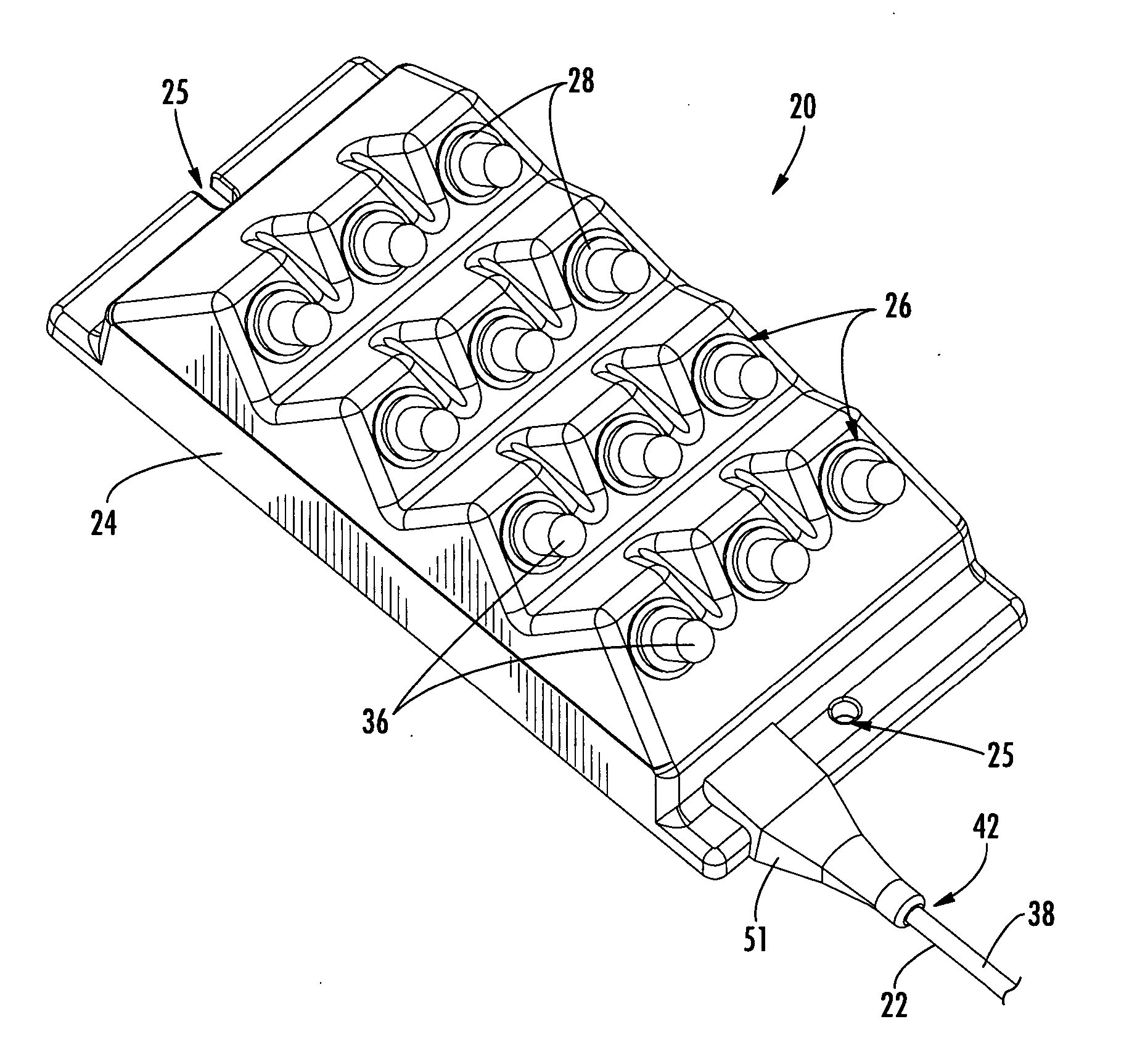
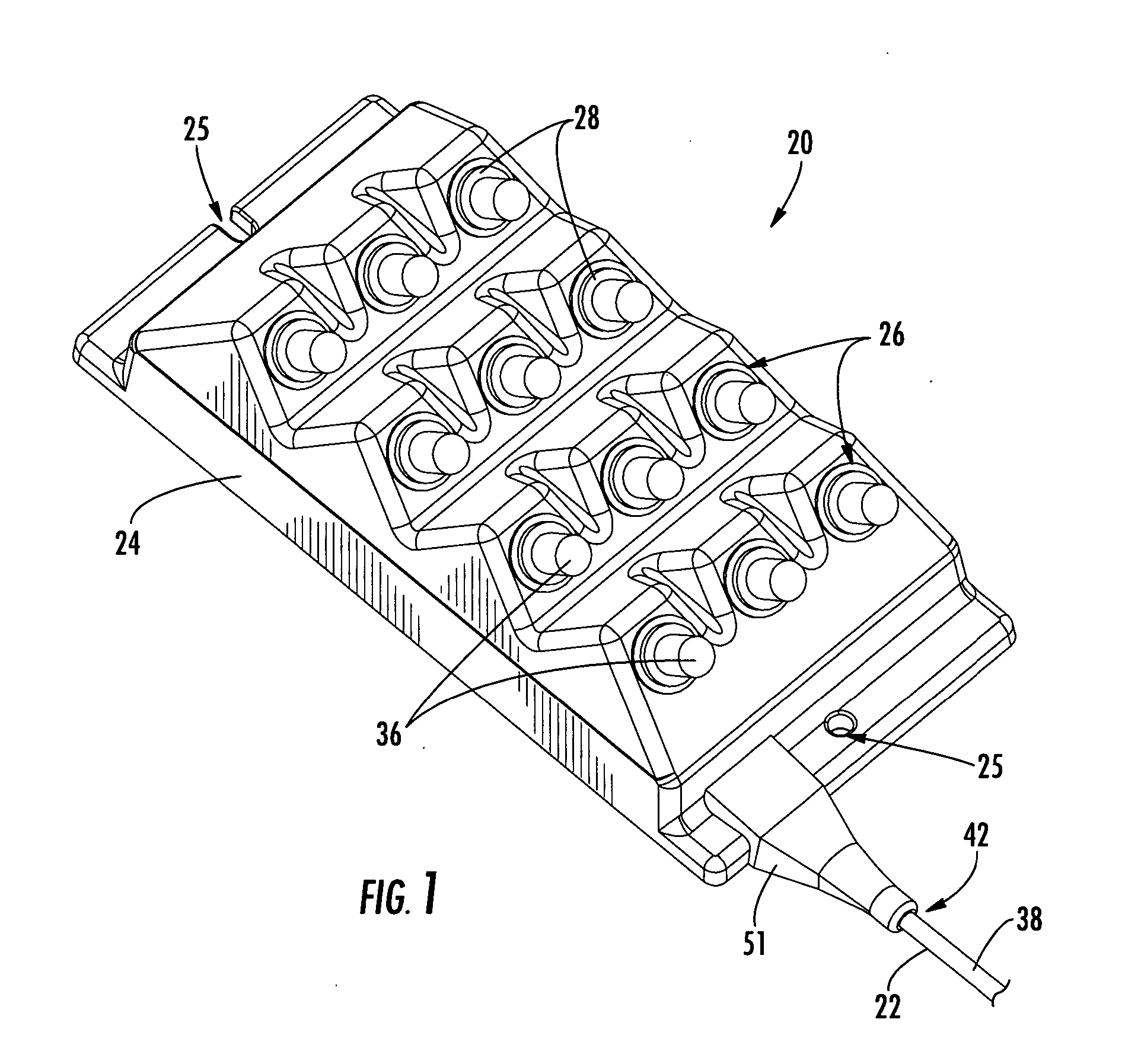
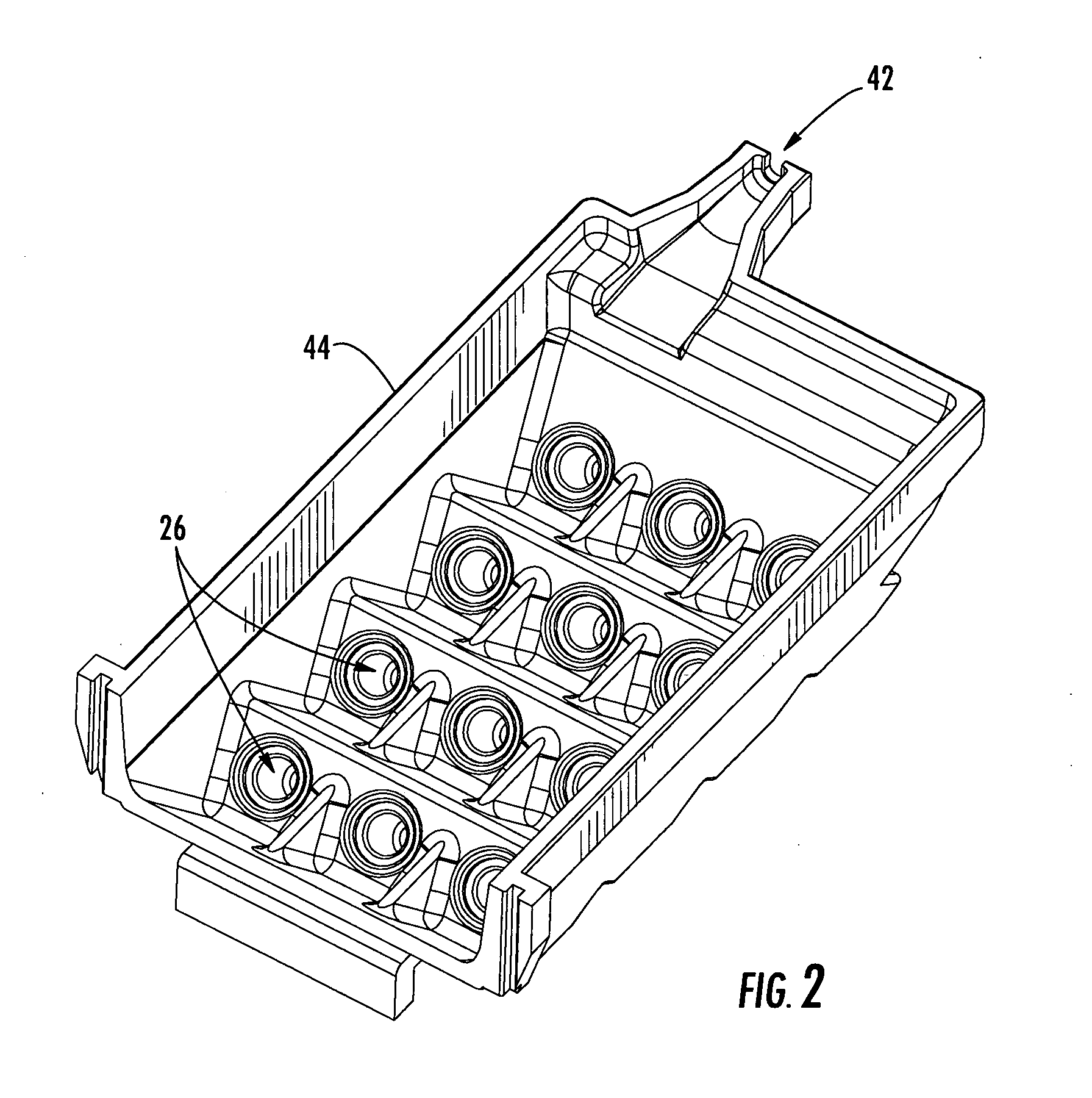
[0029] The present invention provides various embodiments of an overmolded multi-port optical connection terminal, also referred to herein as a “multi-port terminal,”“overmolded terminal” or “terminal,” for a fiber optic communications network comprising a tether cable having a first end adapted to be attached to a fiber optic distribution cable and a ...


PUM


Abstract

An overmolded multi-port optical connection terminal for a fiber optic distribution cable includes a tether cable containing a plurality of optical fibers optically connected to a corresponding plurality of optical fibers terminated from the fiber optic distribution cable at a first end of the tether cable, an overmolded housing a the second end of the tether cable, at least one connector port, and plenum means for accommodating excess fiber length (EFL) caused by shrinkage of the tether cable and/or pistoning of the optical fibers of the tether cable during connector mating. In one embodiment, a centralized plenum means is defined by an internal cavity within the overmolded housing sufficient for accommodating the EFL without micro bending. In another embodiment, a distributed plenum means is defined by an oversized tubular portion of the tether cable having an inner diameter sufficient for accommodating the EFL without micro bending.

Description

BACKGROUND OF THE INVENTION [0001] 1. Field of the Invention [0002] The present invention relates generally to an optical connection terminal for use in a fiber optic communications network, and more particularly, to an overmolded multi-port optical connection terminal including a tether cable, an overmolded housing, at least one connector port, and plenum means for accommodating excess fiber length (EFL). [0003] 2. Description of the Related Art [0004] Optical fiber is increasingly being used for a variety of broadband communications including voice, video and data transmissions. As a result of the increase in demand for broadband communications, fiber optic networks typically include a large number of mid-span access locations at which one or more optical fibers are terminated or “branched” from a distribution cable. The mid-span access locations provide an interconnection point, also referred to herein as a “tap point,” from the distribution cable leading to a network distributio...

Claims


Application Information

Patent Timeline
IPC IPC(8): G02B6/00G02B6/36
CPCG02B6/4441
Inventor LUTHER, JAMES P.ELKINS, ROBERT B. IINIELSEN, LARS K.
Owner CORNING OPTICAL COMM LLC
Why Eureka
Try Eureka