System and method for slot deflection routing at optical router/switch

a data packet and optical router technology, applied in data switching networks, multiplex communication, digital transmission, etc., can solve the problems of current routers/, data traffic cannot be routed to intermediate edge units, current routers/, etc., to reduce the underutilization of links

Inactive Publication Date: 2006-07-06
UNWIRED BROADBAND INC
View PDF26 Cites 17 Cited by
  • Summary
  • Abstract
  • Description
  • Claims
  • Application Information

AI Technical Summary

Benefits of technology

[0005] The present invention provides an optical data packet routing system and method that substantially eliminates or reduces disadvantages and problems associated with previously developed optical data packet systems and methods.
[0007] The present invention provides substantial technical advantages over previously developed systems and methods of routing optical data packets by allowing data packets on saturated links between edge units to be rerouted rather than being dropped.
[0008] The present invention provides another advantage over previously developed methods and systems of routing optical data packets by allowing a new schedule pattern to be established in response to increases in traffic without dropping data packets.
[0009] The present invention provides yet another advantage over previously developed systems and methods of routing optical data packets by rerouting data packets around faults in optical routers or switches.
[0010] The present invention provides yet another substantial technical advantage over previously developed systems and methods of routing optical data packets by decreasing the underutilization of links in an optical router or switch.

Problems solved by technology

Therefore, if there is an unexpected increase in traffic going to a particular egress edge unit, current routers cannot effectively allocate more router capacity to links between the ingress edge unit and the egress edge unit to which the increased traffic is bound.
Additionally, in current routers / switches, data traffic can not be routed to intermediate edge units in the router / switch prior to being sent to the destination egress edge unit.
Because bandwidth can not be reallocated between ingress interface ports and egress interface ports and data traffic can not be rerouted to intermediate edge units, current routers / switches have no option but to drop excess traffic.
Furthermore, because data traffic cannot be rerouted to the intermediate edge units, if there is a fault on the links between the ingress edge unit and egress edge unit, data traffic bound for the egress edge unit must also be dropped.
Thus, current routers / switches can not adequately compensate for permanent or transient increases in traffic or for the failure of links within the router.

Method used


Image

  • System and method for slot deflection routing at optical router/switch
  • System and method for slot deflection routing at optical router/switch
  • System and method for slot deflection routing at optical router/switch

Examples


Embodiment Construction

[0019] Embodiments of the present invention are illustrated in the FIGURES, like numerals being used to refer to like and corresponding parts of the various drawings.

[0020] The present invention provides a system and method for routing data packets through an intermediate edge unit (e.g., non-destination edge unit) at a router / switch prior to routing the data packet to its destination edge unit. Because data packets can be re-routed to intermediate edge units based on the traffic conditions being experienced by the router, embodiments of present systems can provide effective traffic and fault management. Furthermore, by being able to allocate capacity to links in the router with more traffic, embodiments of the present invention can increase the traffic fill ratios experienced by the router.

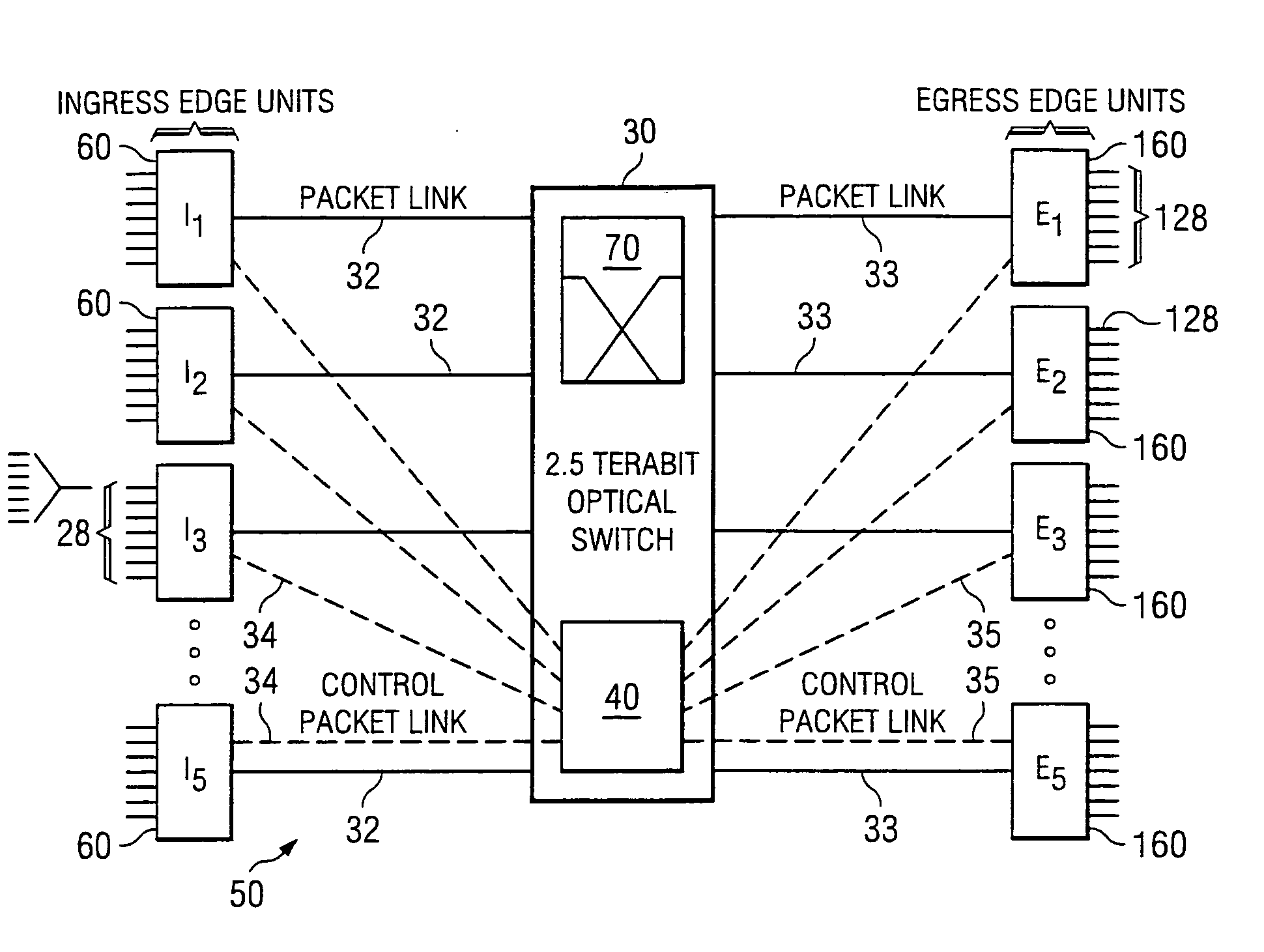
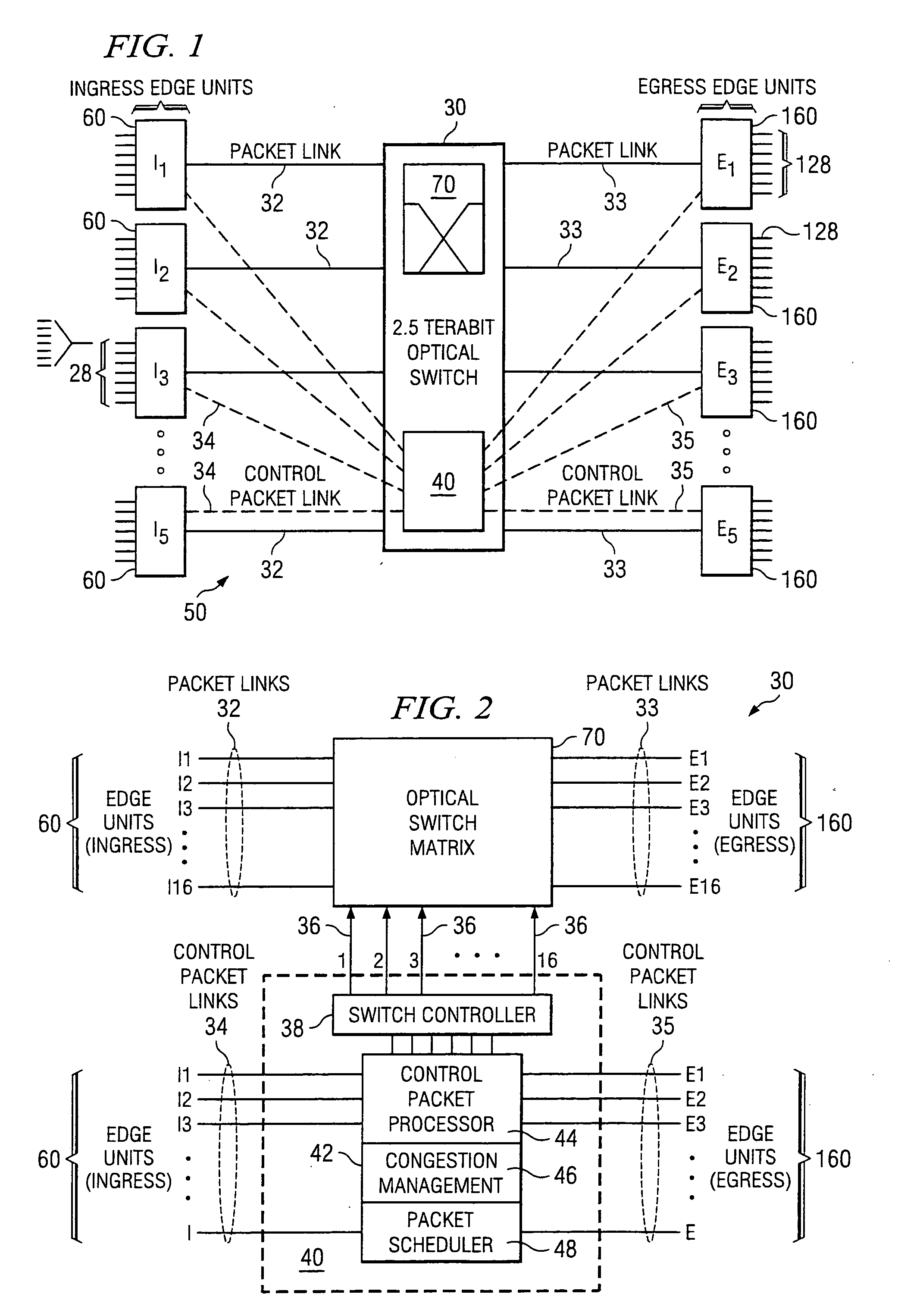
[0021]FIG. 1 is a diagrammatic representation of one embodiment of an optical router 50 configurable to provide slot deflection routing according to the present invention. The optical router 50...


PUM


Abstract

The present invention provides a system and method for slot deflection routing of optical data packets. The method of the present invention includes the steps of establishing a schedule pattern that includes a plurality of time slots. The schedule pattern includes at least one time slot in which an ingress edge unit can communicate with a destination egress edge unit, at least one time slot in which the ingress edge unit can communicate with a intermediate edge unit, and at least one time slot in which the intermediate edge unit can communicate with the destination egress edge unit. The present invention also includes receiving a data packet at the ingress edge unit and determining if the schedule pattern allocates sufficient bandwidth to send the data packet from the ingress edge unit to the destination egress edge unit without deflecting the data packet through an intermediate edge unit. If enough bandwidth has been allocated, the data packet can be sent to the destination edge unit from the ingress edge unit without deflection. Alternatively, if enough bandwidth has not been allocated, the data packet can be deflected to an intermediate edge unit prior to being communicated to the destination egress edge unit.

Description

CROSS REFERENCE TO RELATED APPLICATIONS [0001] This application is a continuation in part of U. S. patent application Ser. No. 09 / 698,666, entitled “Non-Blocking, Scalable Optical Router Architecture and Method for Routing Optical Traffic,” filed Oct. 27, 2000, which is hereby fully incorporated by reference herein.TECHNICAL FIELD OF THE INVENTION [0002] The present invention relates generally to the routing of data packets and more particularly to a system and method for slot deflection routing of data packets in an optical router. BACKGROUND OF THE INVENTION [0003] The emergence of the Internet and the reliance by businesses and consumers on the transfer of data in an increasing number of daily activities requires that telecommunications networks and components deliver ever greater amounts of data at faster speeds. In telecommunications networks, data packets can be directed through the network by a series of routers and switches. At each router / switch in the network, data packets...

Claims


Application Information

Patent Timeline
Patent Type & Authority Applications(United States)
IPC IPC(8): H04J14/00H04L12/56H04Q11/00
CPCH04L45/00H04L45/302H04L45/62H04L47/10H04L47/2433H04L47/2441H04L47/33H04L49/101H04L49/1523H04L49/205H04L49/254H04L49/3009H04L49/3081H04L49/357H04L49/503H04L2012/5662H04Q11/0005H04Q11/0062H04Q11/0066H04Q11/0071H04Q2011/0024H04Q2011/0033H04Q2011/0039H04Q2011/005H04Q2011/0073H04Q2011/0079H04Q2011/0084
Inventor AICKLEN, GREGORY H.TAMIL, LAKSHMAN S.
Owner UNWIRED BROADBAND INC
Why Eureka
Try Eureka