
System and method of establishing an electrical connection between an implanted lead and an electrical contact

a technology of electrical coupling and implanted leads, which is applied in the field of system and method of electrical coupling an implanted lead and an electrical contact, can solve the problems of difficult connection, difficulty in machining the upper and lower lip, and often failing to consistently provide adequate electrical coupling between the connectors, etc., and achieves the effect of reducing disadvantages and problems or reducing disadvantages

Inactive Publication Date: 2005-05-19
ADVANCED NEUROMODULATION SYST INC
View PDF9 Cites 44 Cited by
  • Summary
  • Abstract
  • Description
  • Claims
  • Application Information

AI Technical Summary

Benefits of technology

The present invention provides a system for connecting an implantable lead to a tissue stimulation device using an electrical contact. The contact includes a conductive disc with inner and outer perimeters and conductive projections that flex to maintain the lead in a fixed position relative to the disc. The system also includes an implantable receiver that delivers electrical energy to tissues proximate to the lead. The technical effects of this invention include reducing disadvantages and problems associated with previous solutions, improving the stability and reliability of the electrical connection, and minimizing the risk of lead dislodgement or migration.

Problems solved by technology

These prior art connectors often fail to consistently provide adequate electrical coupling with the lead or are difficult to connect to the lead.
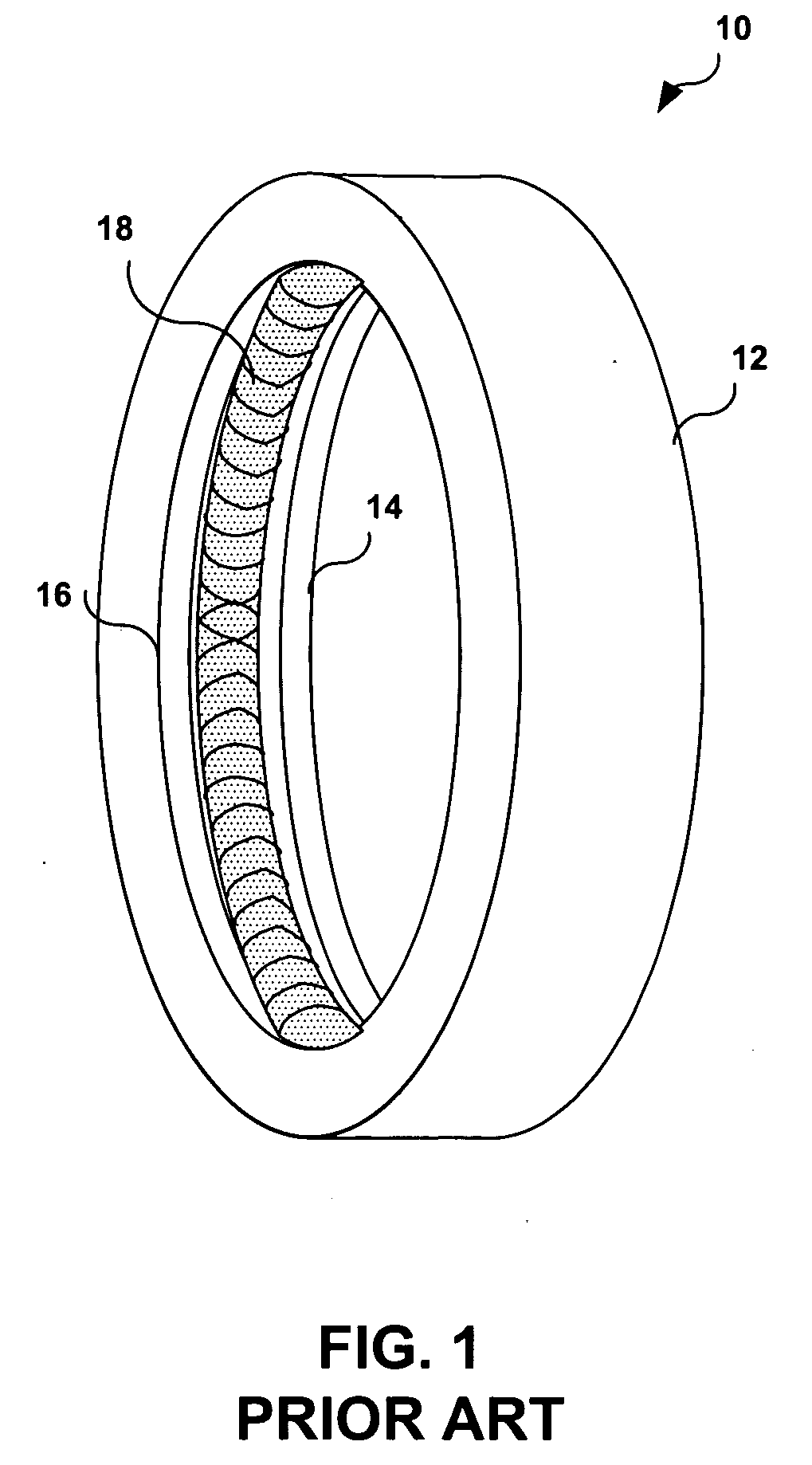
Some problems associated with this solution are the difficulty in machining the upper and lower lip to retain the contact spring 18, as well as placing the spring within band 12.
Associated with these difficulties is a high cost of manufacturing.
This process is difficult and time consuming.
This surgery places undue physical, mental, and financial strains on the patient.

Method used


Image

  • System and method of establishing an electrical connection between an implanted lead and an electrical contact
  • System and method of establishing an electrical connection between an implanted lead and an electrical contact
  • System and method of establishing an electrical connection between an implanted lead and an electrical contact

Examples


Embodiment Construction

[0021] Preferred embodiments of the present invention are illustrated in the figures, like numerals being used to refer to like and corresponding parts of the various drawings

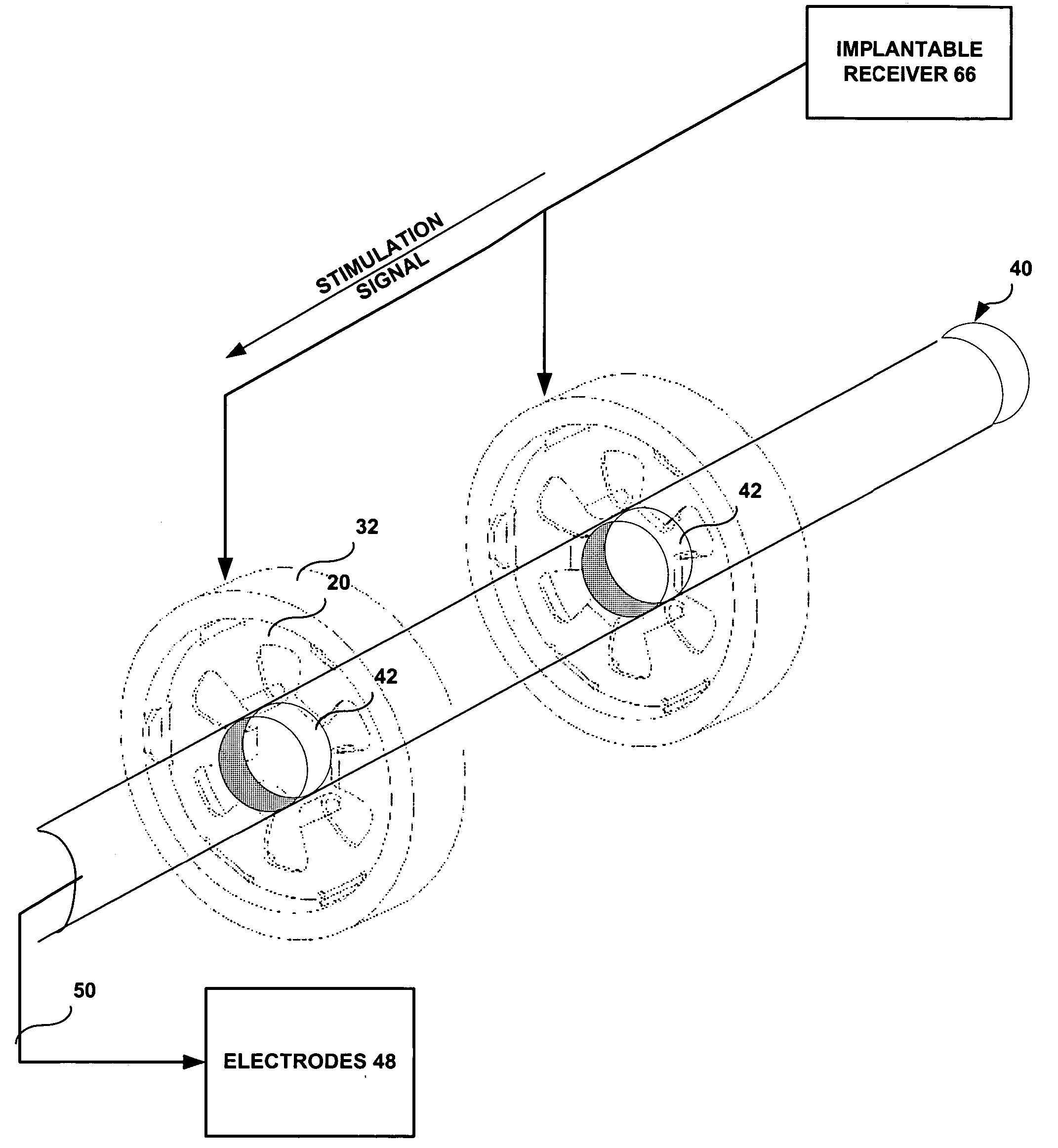
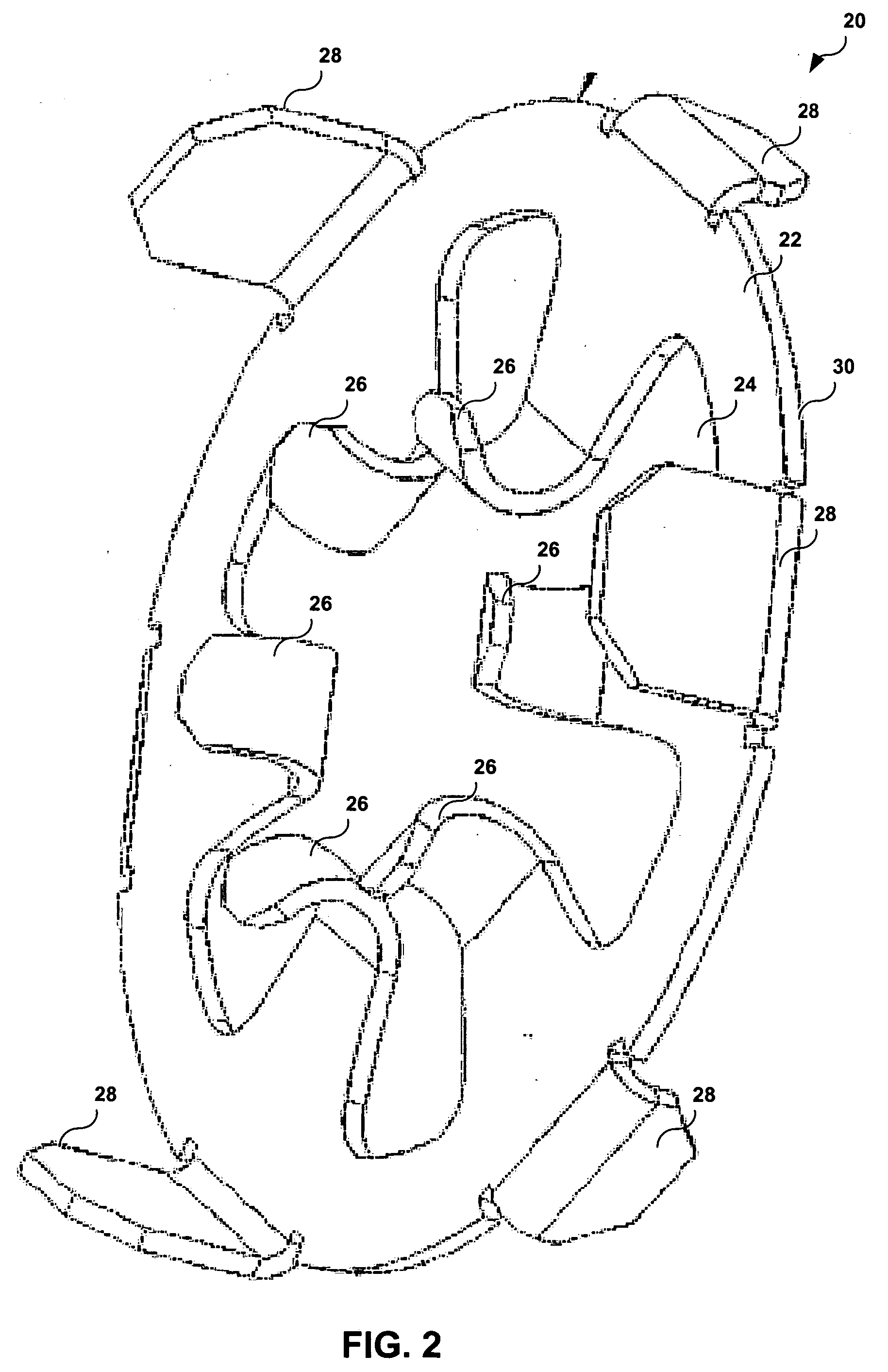
[0022]FIG. 2 provides a pictorial representation of electrical contact 20 that greatly reduces the cost of manufacturing and simplifies the surgical implantation. The contact forms part of the electrical circuit that operably couples an implantable lead and a controller or processing module. The implantable lead will be discussed in further detail as depicted in FIG. 5. The contact operably couples the implantable lead to a tissue stimulation device.

[0023] The electrical contact is formed from a conductive disc 22 having an inner aperture 24 and conductive projections 26 (or fingers) that extend away from the inner aperture. The number of conductive projections corresponds to the number of contacts on the lead, which may correspond to the number of electrodes located on the lead.

[0024] The conductive disc 22...


PUM


Abstract

An electrical contact to electrically couple epidural stimulation leads to a tissue stimulation device. This electrical contact includes a conductive disc having an inner aperture that is electrically and operably coupled to the tissue stimulation device. A number of conducted projections extend inward from the inner aperture of the disc and flex elastically to receive an epidural stimulation lead. These conductive projections electrically couple with a number of terminals within the epidural stimulation lead. Tension exerted by flexing the conducted projections maintains the epidural stimulation lead in a relatively fixed position relative to the electrical contact. A number of projections at the outer perimeter of the conductive disc electrically and operably couple the conductive disc to a conductive housing wherein the conductive housing is electrically and operably coupled to the tissue stimulation device.

Description

TECHNICAL FIELD OF THE INVENTION [0001] The present invention relates generally to electrical contacts, and more particularly, a system and method for electrically coupling an implanted lead with an electrical contact. BACKGROUND OF THE INVENTION [0002] Electrical stimulation of the spinal cord or peripheral nerves can result in pain reduction and / or elimination. Medical leads having electrodes are often implanted near the spinal column to provide pain relief for chronic intractable pain. The electrodes stimulate tissue within the spinal column to reduce pain sensations at other parts of the body. The stimulation signals applied can be optimized for pain reduction or elimination depending on the location of the pain. [0003] The area of excitation and the intensity of excitation vary according to the stimulation signals. To vary the area of excitation, an array of electrodes implanted near nerve tissue can be configured for a positive, negative, or neutral polarity such that the desi...

Claims


Application Information

Patent Timeline
Patent Type & Authority Applications(United States)
IPC IPC(8): A61N1/05A61N1/18A61N1/375
CPCA61N1/3752A61N1/0551
Inventor DAGLOW, TERRYJONES, ROBERT
Owner ADVANCED NEUROMODULATION SYST INC
Learn More