
Protection circuit module and battery pack incorporating the same

a protection circuit and battery pack technology, applied in the field of protection circuit modules, can solve the problems of increasing the manufacturing cost of the battery pack, deteriorating efficiency, etc., and achieve the effect of increasing cost and simple structur

Inactive Publication Date: 2006-07-06
ROHM CO LTD
View PDF7 Cites 5 Cited by
  • Summary
  • Abstract
  • Description
  • Claims
  • Application Information

AI Technical Summary

Benefits of technology

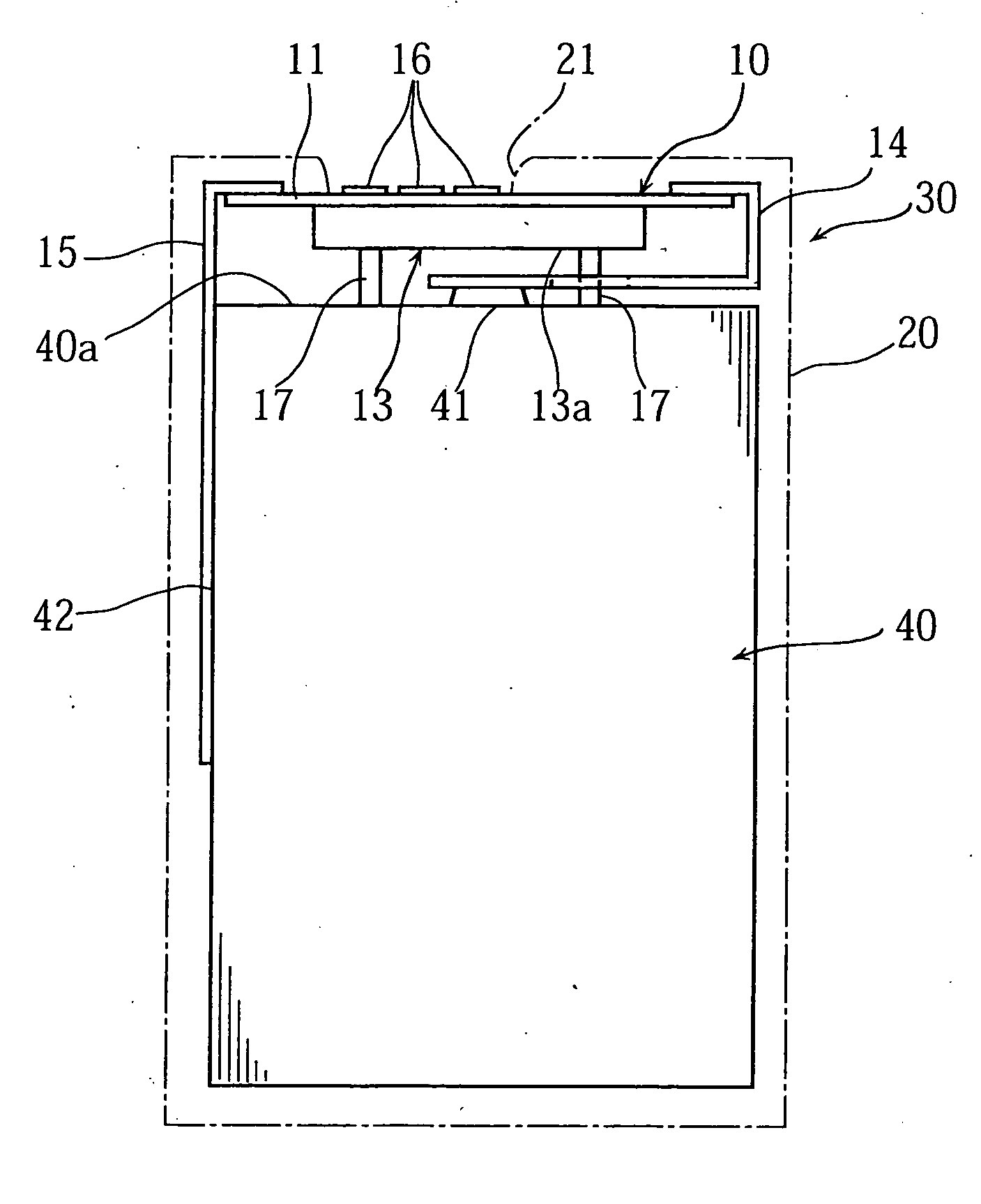
The present invention provides a protective circuit module and a battery pack with the module. The module has a simple structure without increasing cost and prevents shorting contact between the battery and the module during assembly. The module includes a substrate, an electronic component, a molding, and terminal plates for connecting to the battery. The molding has a cover surface with a projection for positioning the module. The battery pack has a case and the protective circuit module positioned by the projection of the molding. The invention ensures proper positioning of the module and battery during assembly.

Problems solved by technology

However, such a coping method increases the number of parts of the battery pack 30 and deteriorates the efficiency in assembling the pack, which results in an increase in the manufacturing cost of the battery pack.

Method used


Image

  • Protection circuit module and battery pack incorporating the same
  • Protection circuit module and battery pack incorporating the same
  • Protection circuit module and battery pack incorporating the same

Examples


Embodiment Construction

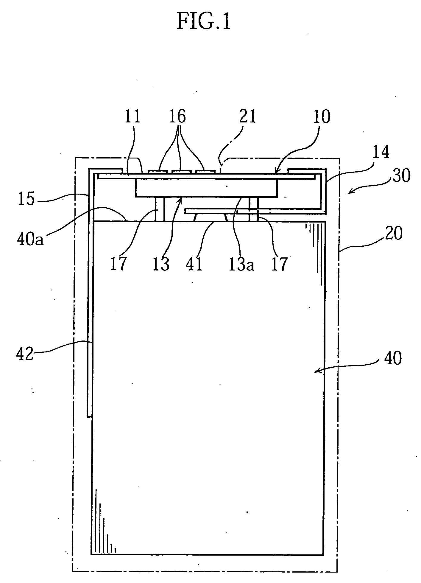
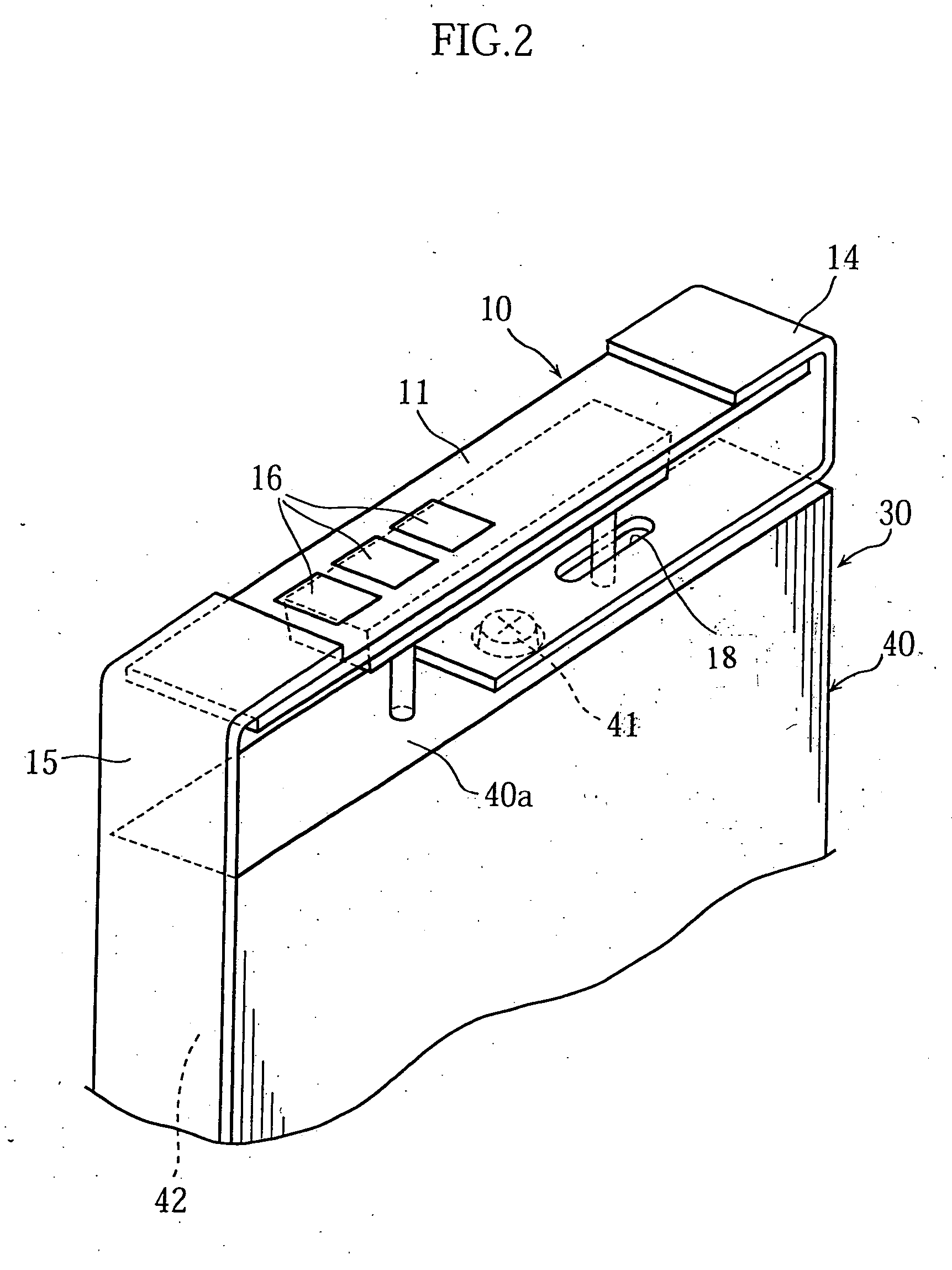
[0029] Preferred embodiments of the present invention will be described below in detail with reference to FIGS. 1-7. In these figures, parts or portions which are identical or similar to those of the prior art structure shown in FIG. 8 are designated by the same reference signs.

[0030]FIG. 1 schematically illustrates a battery pack 30 embodying the present invention, which comprises a casing 20 accommodating a protective circuit module 10 together with a rechargeable battery 40.

[0031] The protective circuit module 10 has a basic structure wherein electronic components 12 for constituting a protective circuit are mounted on one surface of an insulating substrate 11 formed of e.g. glass-fiber-reinforced epoxy resin as sealed in a molding 13, while conductor plates 14 and 15 each has an end connected to the substrate 11 for connecting the protective circuit to the rechargeable battery 40. Specifically, the substrate 11 comprises a short plate strip having a width corresponding to the ...


PUM

PropertyMeasurementUnit
charging currentaaaaaaaaaa
discharging currentaaaaaaaaaa
thicknessaaaaaaaaaa

Abstract

The protective circuit module includes a substrate, electronic components mounted on the substrate for constituting a protective circuit, a molding formed on the substrate to enclose the electronic components, and terminal plates connected to appropriate portions of the substrate for connecting the protective circuit to a rechargeable battery. The molding includes a cover surface oriented opposite to the substrate and projections integrally formed on the cover surface to project therefrom.

Description

[0001] This application is a continuation of application Ser. No. 10 / 328,732, filed Dec. 23, 2002, entitled PROTECTION CIRCUIT MODULE AND BATTERY PACK INCORPORATING THE SAME, which application(s) are incorporation herein by reference.BACKGROUND OF THE INVENTION [0002] 1. Field of the Invention [0003] The present invention relates to a protection circuit module for a rechargeable battery and to a battery provided with such a protective circuit module. [0004] 2. Description of the Related Art [0005] A battery pack for use as a rechargeable power source of portable terminal equipment such as a cellular phone is provided with a protective circuit for preventing a rechargeable battery from overcharging or over discharging. For convenience in assembling the battery pack, such a protective circuit is generally provided as a module. [0006]FIG. 8 schematically illustrates an example of battery pack 30 comprising such a conventional protective circuit module 10 and a rechargeable battery 40 w...

Claims


Application Information

Patent Timeline
Patent Type & Authority Applications(United States)
IPC IPC(8): H01M2/00H02H7/00H01M6/50H01M10/04H01M10/42H01M10/46H01M50/588H01M50/591H02J7/00
CPCH01M2/34H01M10/0436H01M10/425H01M2200/00Y02E60/10Y02P70/50H01M50/588H01M50/591
Inventor NISHIMURA, KOSHINAGASHIMA, MITSUNORI
Owner ROHM CO LTD
Learn More