Remote web access control of multiple home comfort systems

a technology for home comfort and remote access, applied in the field of system and method for remotely accessing comfort systems, can solve the problem that existing home comfort remote access systems can only access a single system

Inactive Publication Date: 2006-07-06
CARRIER CORP
View PDF18 Cites 104 Cited by
  • Summary
  • Abstract
  • Description
  • Claims
  • Application Information

AI Technical Summary

Problems solved by technology

The problem is that existing home comfort remote access systems can only access a single system at a single location.

Method used


Image

  • Remote web access control of multiple home comfort systems
  • Remote web access control of multiple home comfort systems
  • Remote web access control of multiple home comfort systems

Examples


example 1

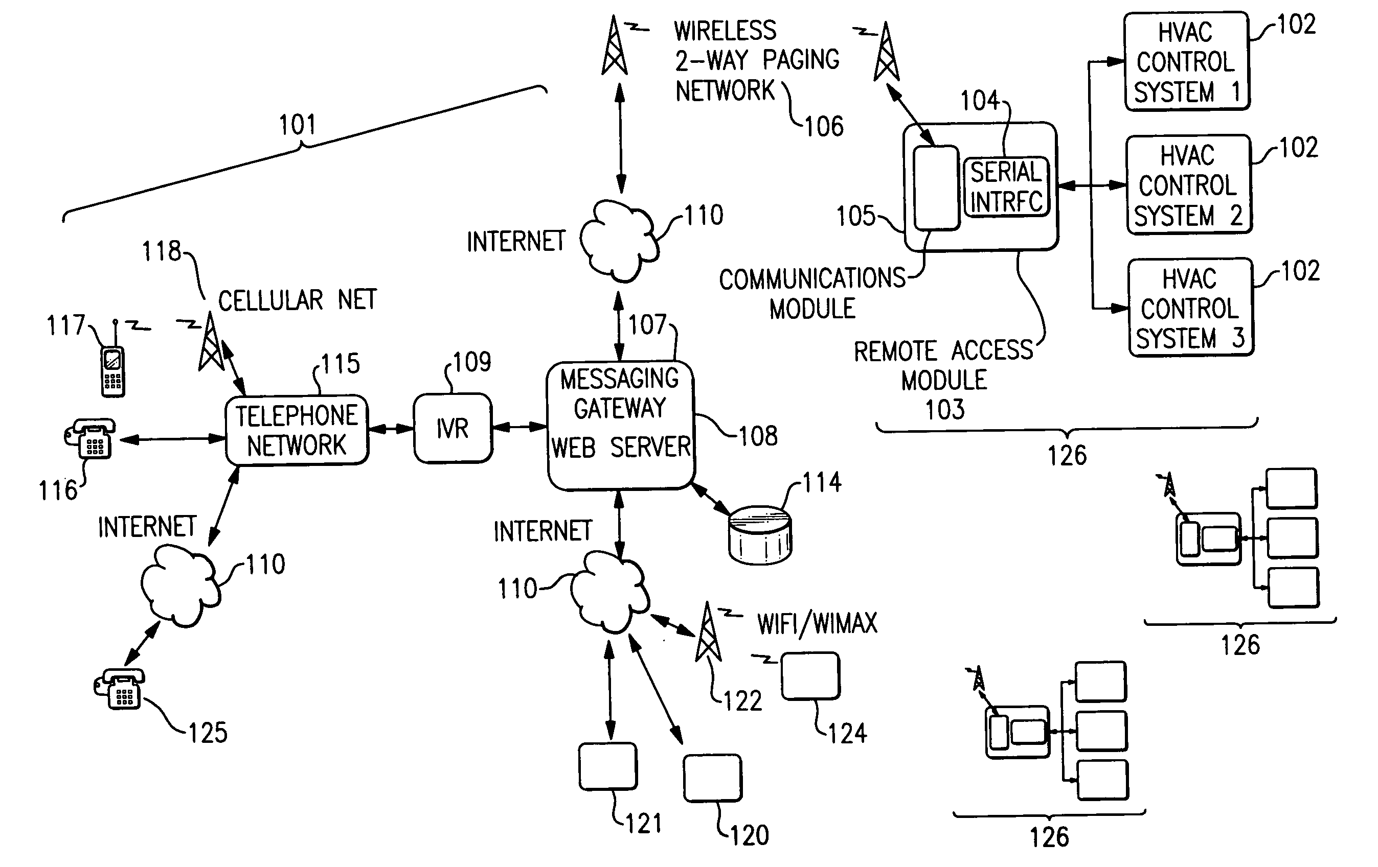
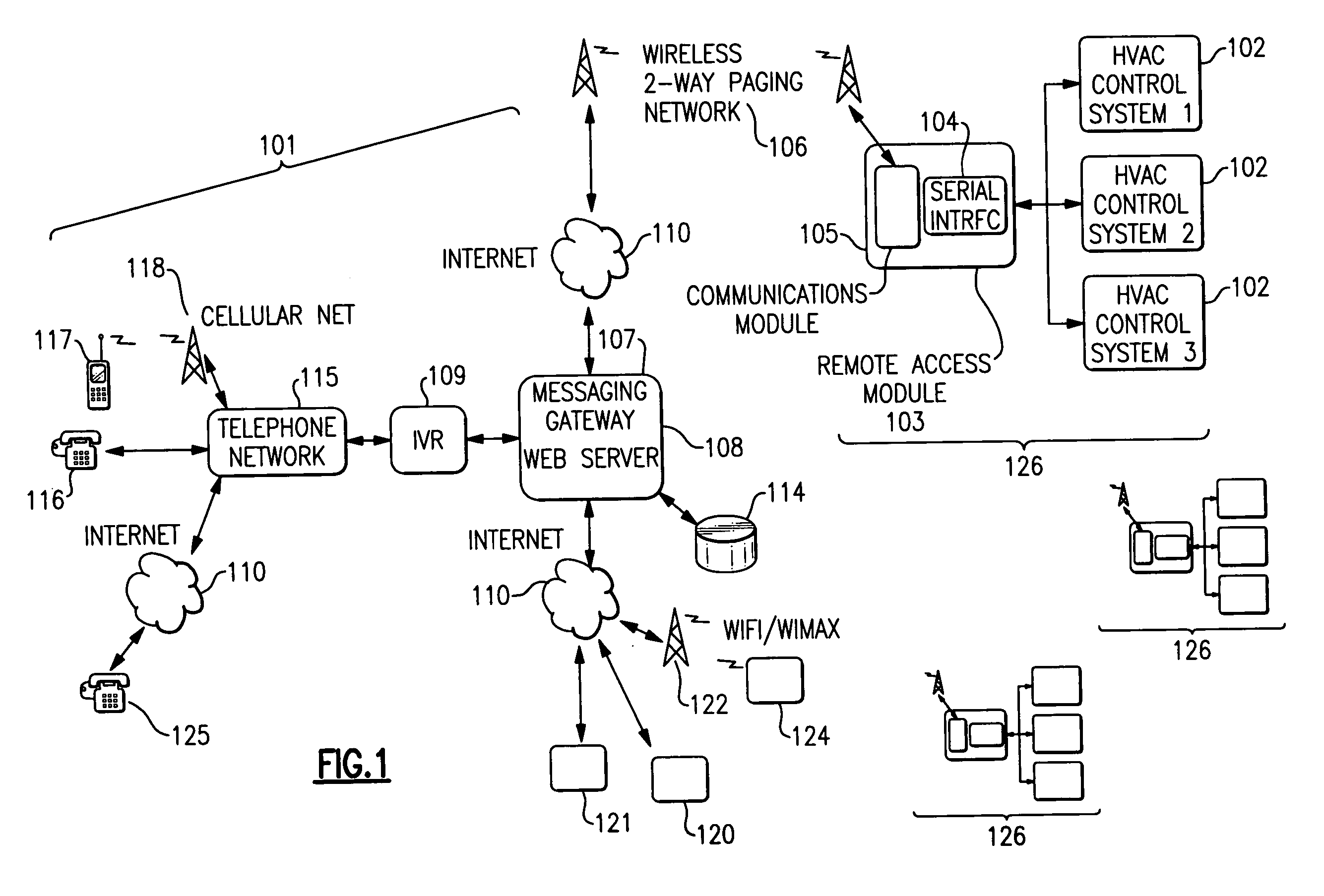
[0044] Example 1 is based on FIG. 5 showing an exemplary embodiment of a system 101 accessed by Internet connection. In this example, a consumer accesses location 2, a home. System 2506 is designated as the “PlayArea”. Zone 1509 is the “Pool Room”, Zone 2510 is the “Game Room”510, and Zone 8511 is the “Sun Room”. The exemplary system shown in FIG. 5 is now compared to the system diagram of FIG. 1. The consumer's profile, including login, location, system, and zone information can be stored as consumer profile record 503 in database 504 on data storage element 114.

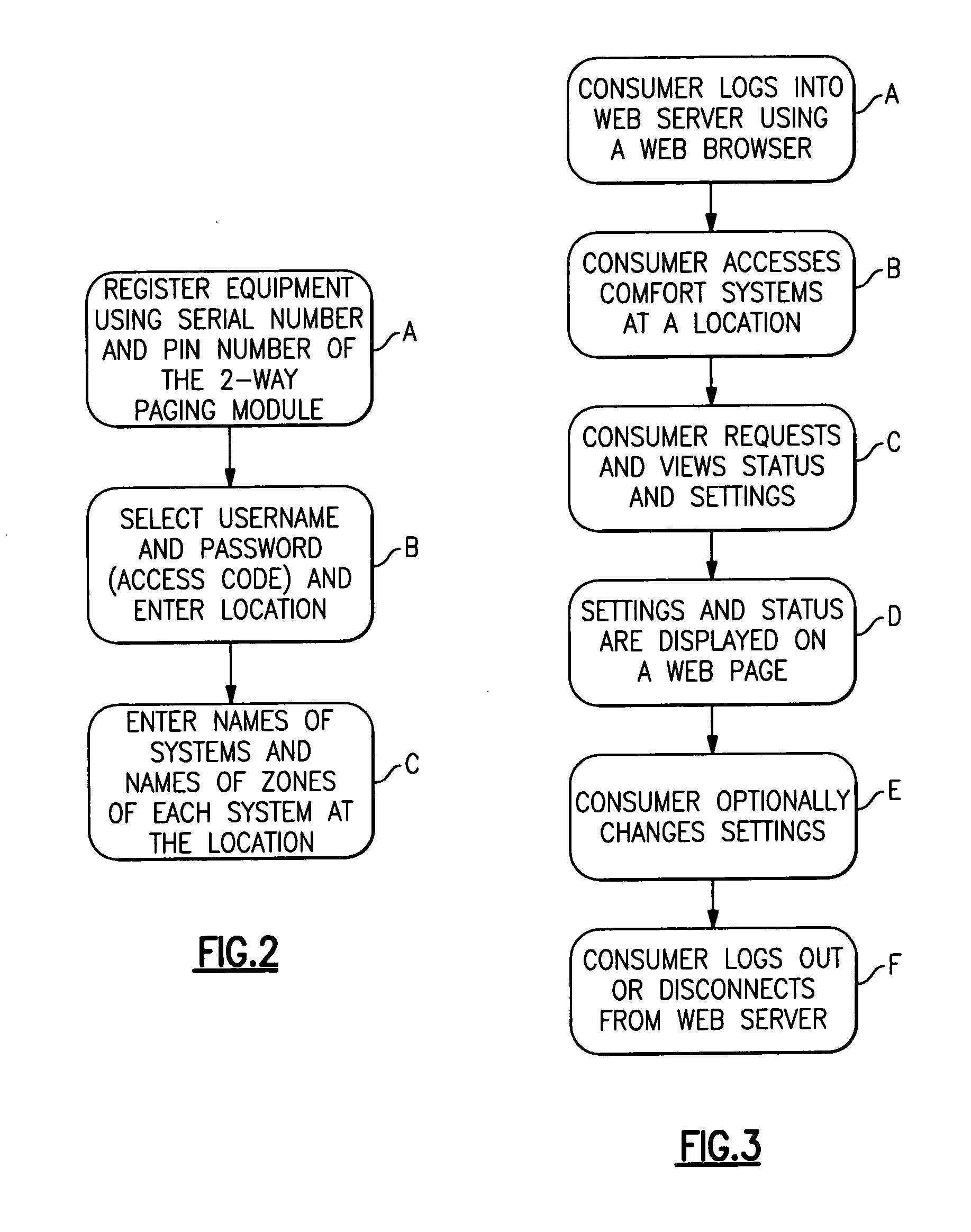
[0045] The consumer accesses the system via the web, using web browser 502. FIG. 6 shows a web browser page used in this example for consumer login according to step FIG. 3, step A. Web browser 502 can be running on any fixed, portable, or mobile computer or terminal platform capable of running a suitable browser such as PC 121 in FIG. 1. Web server 108 comprises the web pages to be displayed to the consumer, a database in...

example 2

[0047] Example 2 is based on FIG. 8 showing an exemplary embodiment of a system 101 accessed by telephone through a telephone network 115 and IVR 109. In this example, a consumer accesses location 2, a home. System 2506 is designated as the “PlayArea”. Zone 1509 is the “Pool Room”, Zone 2510 is the “Game Room”510, and Zone 8511 is the “Sun Room”. The exemplary system shown in FIG. 8 is now compared to the system diagram of FIG. 1. The consumer's profile, including login, location, system, and zone information can be stored as consumer profile record 503 in database 504 on data storage element 114.

[0048] The consumer accesses the system via a telephone instrument 803. Telephone instrument 803 can be a wired telephone 116, a cell phone 117, a VOIP based phone 125, or other telephone instrument capable of sending telephone touch tones and voice, and receiving voice, via telephone network 115.

[0049] After dialing a telephone number, advantageously a toll free number, IVR 109 presents ...

example 3

[0051] Example 3 is based on FIG. 9 showing an exemplary embodiment of a system 101 generating notifications by email service and / or by telephone through IVR 109. FIG. 9 shows a system for example 3, similar to the systems discussed with examples 2 and 3. In this example, there is a low temperature detected in the Pool zone which generates an urgent low temperature notification. A grid similar to that shown in FIG. 10 was set up to send urgent notifications as follows: an email and phone notification is made to the consumer and also sent as a phone notification to the dealer. The consumer's profile, including login, location, system, and zone information and the notification grid, can be stored as consumer profile record 503 in database 504 on data storage element 114.

[0052] System 2506 for the play area detects a low temperature in pool zone 1509. System 2506 generates an urgent low temperature notification sent by wireless pager from the home location 507 via wireless network and...


PUM


Abstract

A system allows a consumer to remotely access the status and settings of multiple home comfort systems via the Internet. The system comprises, a web server connected to the Internet. The web server is programmed to access the multiple home comfort systems and has a data storage device, a connection to the Internet to communicate with the consumer, and a messaging gateway coupled to a network to communicate with the multiple home comfort systems. At least one remote access module is connected to multiple home comfort systems. The remote access module communications with the web server via the network, and the messaging gateway. A consumer Internet device is connected to the Internet to allow the consumer to communicate with the web server, wherein the consumer can remotely access and control the multiple home comfort systems via the web server.

Description

CROSS REFERENCE TO RELATED APPLICATIONS [0001] This application claims the benefit of U.S. Provisional Application Ser. No. 60 / 640,276, “Remote Access Control And Notifications Of Multiple Home Comfort Systems”, filed Dec. 30, 2004. The 60 / 640,276 provisional application is incorporated by reference herein.FIELD OF THE INVENTION [0002] This invention relates to a system and method for remotely accessing comfort systems and more particularly to remotely access multiple comfort systems in multiple locations to obtain remote status reports, access and change settings. BACKGROUND OF THE INVENTION [0003] A consumer can own residences at multiple locations. At each location, the consumer can further own multiple heating, ventilation and air conditioning (“HVAC”) systems. These home comfort (HVAC) systems can comprise furnaces, air conditioners, heat pumps, air filters, ventilators, air cleaners, and humidification control equipment. Many home comfort systems can be expanded further by usi...

Claims


Application Information

Patent Timeline
Patent Type & Authority Applications(United States)
IPC IPC(8): G06F7/00
CPCF24F11/0086F24F2011/0071F24F2011/0069F24F11/30F24F11/57F24F11/58
Inventor ARCHACKI, RAYMOND J. JR.MOORE, JAMES B.
Owner CARRIER CORP
Why Eureka
Try Eureka