
Application status board mitigation system and method

a status board and mitigation system technology, applied in the field of multi-system software/application failure diagnostic systems and methods, can solve the problems of losing valuable software running time, -platform application process, and generally no readily available tools to identify, and achieves the effect of reducing labor costs, quick resolution of issues, and significant labor savings for users

Active Publication Date: 2006-07-06
HULU
View PDF99 Cites 14 Cited by
  • Summary
  • Abstract
  • Description
  • Claims
  • Application Information

AI Technical Summary

Benefits of technology

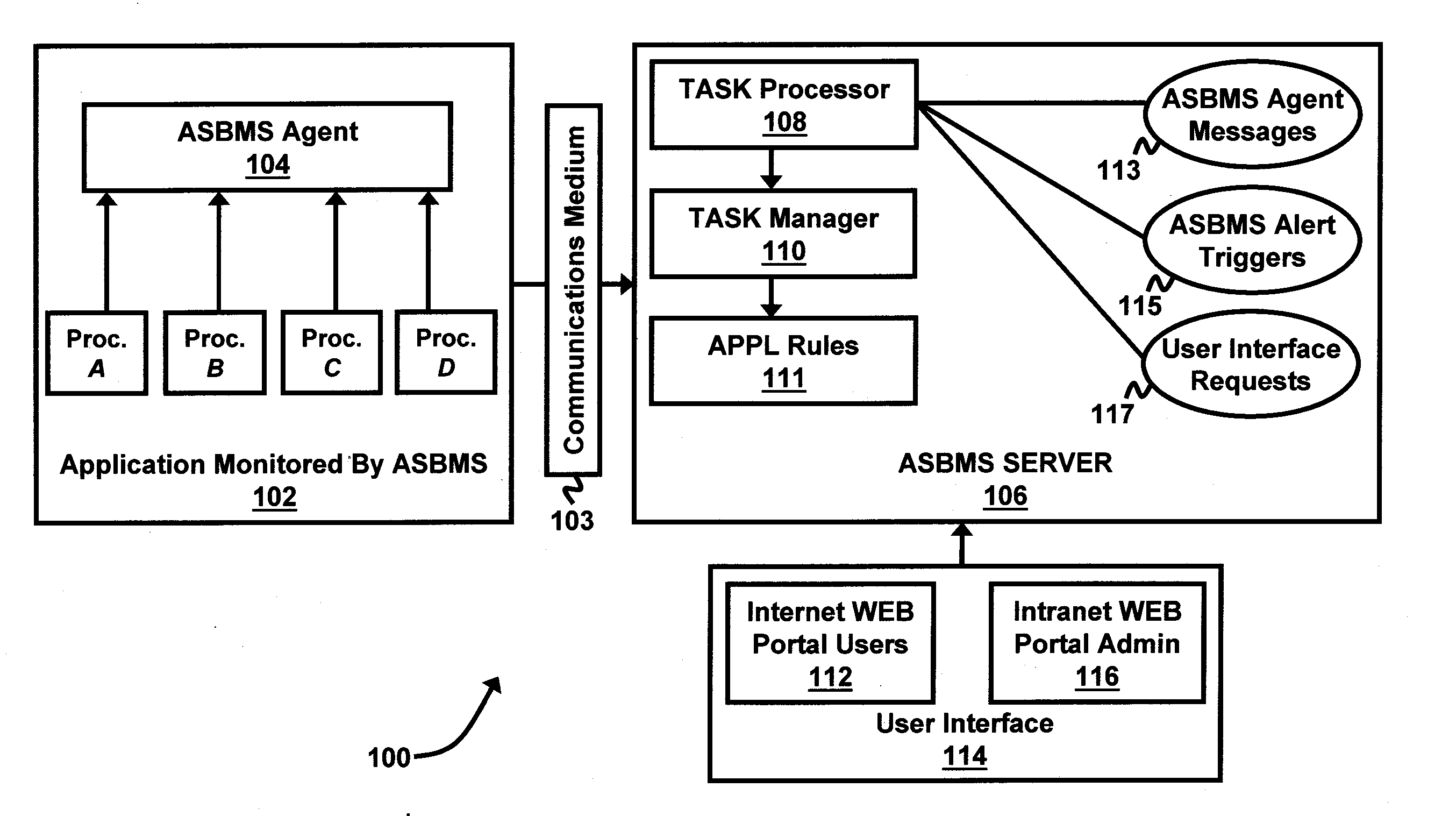
The invention provides a computer monitoring system that can quickly and easily monitor multiple applications and functions on a network of computers. The system uses a rules-driven table to analyze the functional status of applications and sends alerts to a user interface when issues are detected. The system can also predict when an application will be completed and reconcile information across processes. This invention helps streamline operations, save labor, and optimize processing.

Problems solved by technology

Conventionally, when computer software applications are running across multiple systems, one of the problems associated with identifying software malfunctions is that there are generally no readily available tools that can identify, in a cross-platform application process, if jobs (i.e., application protocols) have completed or failed without logging into each individual system and checking on the status of the protocols.
Generally, support personnel have to logon to multiple platforms and research job logs and console messages once a problem is realized in order to determine the status of the application, thereby losing valuable software running time.
However, while Tivoli® is beneficial for the purpose it was designed for, it is generally designed to log job failures and alerts once the failures occur.

Method used


Image

  • Application status board mitigation system and method
  • Application status board mitigation system and method
  • Application status board mitigation system and method

Examples


Embodiment Construction

[0020] The embodiments of the invention and the various features and advantageous details thereof are explained more fully with reference to the non-limiting embodiments that are illustrated in the accompanying drawings and detailed in the following description. It should be noted that the features illustrated in the drawings are not necessarily drawn to scale. Descriptions of well-known components and processing techniques are omitted so as to not unnecessarily obscure the embodiments of the invention. The examples used herein are intended merely to facilitate an understanding of ways in which the embodiments of the invention may be practiced and to further enable those of skill in the art to practice the embodiments of the invention. Accordingly, the examples should not be construed as limiting the scope of the embodiments of the invention.

[0021] As mentioned, there remains a need for a software / application diagnostic tool, which forecasts dependent job time completion or a statu...


PUM


Abstract

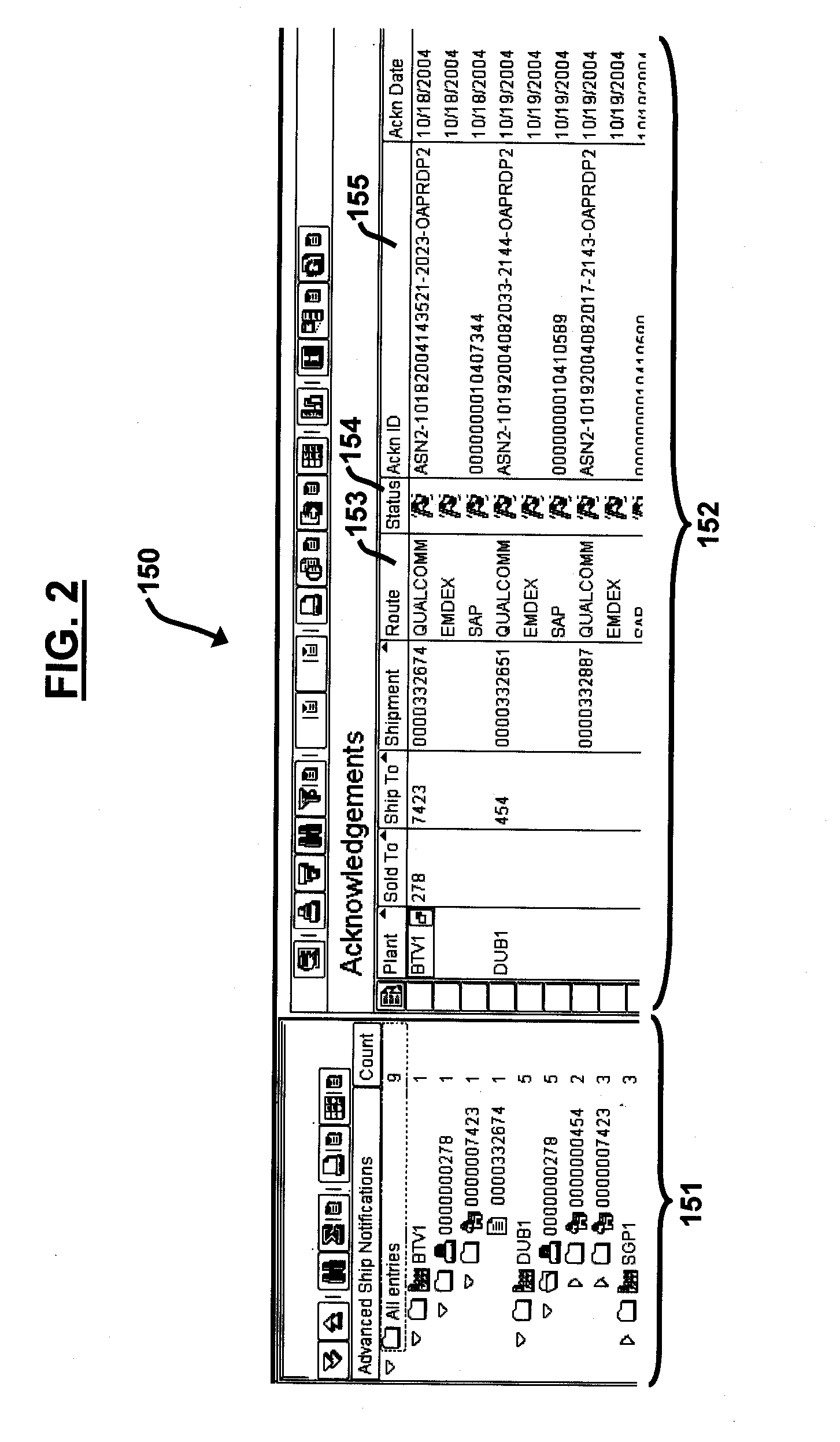
A system and method for monitoring computer applications comprising an application component table comprising a plurality of applications and application functions, wherein the applications comprise data identifying a functional status of the applications; a processor adapted to analyze the functional status of the applications based on the data; and a single status board user interface adapted to display the functional status of the applications, wherein the processor is adapted to predict when a running time of an application will be completed. The processor is adapted to determine whether the application functions fail when the applications are running; diagnose a cause of failure of the application functions; and indicate the cause of failure to a user. The processor is adapted to reconciliate information across processes supporting the applications. The system and method is adapted to send alerts to the single status board user interface of errors found in the processes.

Description

BACKGROUND OF THE INVENTION [0001] 1. Field of the Invention [0002] The embodiments of the invention generally relate to computer diagnostic systems and methods, and more particularly to multi-system software / application failure diagnostic systems and methods. [0003] 2. Description of the Related Art [0004] Conventionally, when computer software applications are running across multiple systems, one of the problems associated with identifying software malfunctions is that there are generally no readily available tools that can identify, in a cross-platform application process, if jobs (i.e., application protocols) have completed or failed without logging into each individual system and checking on the status of the protocols. Generally, support personnel have to logon to multiple platforms and research job logs and console messages once a problem is realized in order to determine the status of the application, thereby losing valuable software running time. As computer technology cont...

Claims


Application Information

Patent Timeline
Patent Type & Authority Applications(United States)
IPC IPC(8): G06F17/00
CPCG06F11/0715G06F11/0751G06F11/3447G06F2201/88
Inventor BRIGHT, MATION S.BURKHARD, SCOTT D.JINDANI, RAHULMCKEE, GREGORY L.PEACHEY-KOUNTZ, PENNY J.SCOTT, JAMES D.
Owner HULU
Learn More