Protective apparel breathing assistance

a technology for protecting clothing and breathing, applied in the field of protective clothing, can solve the problems of repeated complaints of thermal discomfort, fan not sufficiently cooling the person's body, and prone to contamination by doctors in medical environments such as these, and achieve the effects of improving thermal management, low resistance, and low resistan

Inactive Publication Date: 2006-07-13
VERASUIT LLC
View PDF92 Cites 15 Cited by
  • Summary
  • Abstract
  • Description
  • Claims
  • Application Information

AI Technical Summary

Benefits of technology

[0007] The present invention relates to protective apparel that improves thermal management. The protective apparel comprises a set of spacers. Each spacer is arranged on an inner portion of the apparel and maintains apparel proximate to the spacer distant from the person, thereby preventing continuous contact between the person and portions of the apparel. Multiple spacers may form one or more air channel between the spacers, the person and inner portions of the apparel. The channels permit low resistance airflow within the apparel and over the person's body. Low resistance airflow within the channels permits air to be easily moved through the apparel to cool the person.
[0008] The spacers may comprise a compressible material, such as foam. The compressible material reduces forces on the person resulting from contact with an external object. When the compressible material has an elastic memory, elastic return of the material causes each spacer to return to its initial shape after a deforming force is removed. The elastic return thus permits contact between the person or apparel and an external object without compromising airflow and heat management benefits over an extended period of time. This is useful for healthcare practitioners that frequently come in contact with objects such as beds; and when performing actions that require bodily contact, such as nursing assistance of an elderly patient.

Problems solved by technology

Practitioners in medical environments such as these are prone to contamination from airborne, blood-borne and droplet-transmitted biological agents.
The fan does not sufficiently cool the person's body, where the majority of heat is generated.
Thermal discomfort is a repeated complaint for conventional protective apparel.
If the user walks considerably or performs other regular physical tasks, the extra heat generated is not managed—and additionally raises discomfort.
Conventional surgical suits are not intended for prolonged use by mobile individuals.
Similar thermal management issues are found in clean room suits that lack an effective means for managing heat.

Method used


Image

  • Protective apparel breathing assistance
  • Protective apparel breathing assistance
  • Protective apparel breathing assistance

Examples


Embodiment Construction

[0042] The present invention will now be described in detail with reference to a few preferred embodiments thereof as illustrated in the accompanying drawings. In the following description, numerous specific details are set forth in order to provide a thorough understanding of the present invention. It will be apparent, however, to one skilled in the art, that the present invention may be practiced without some or all of these specific details. In other instances, well known process steps and / or structures have not been described in detail in order to not unnecessarily obscure the present invention.

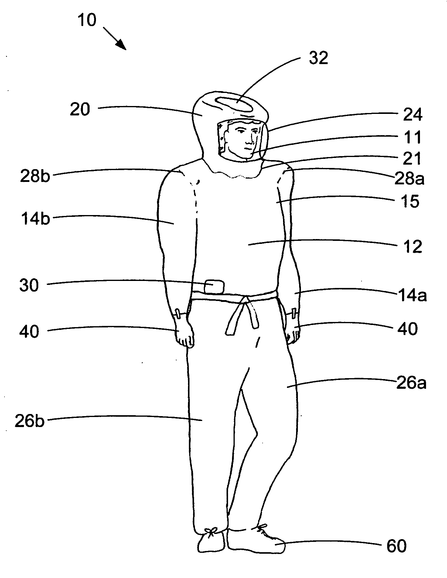
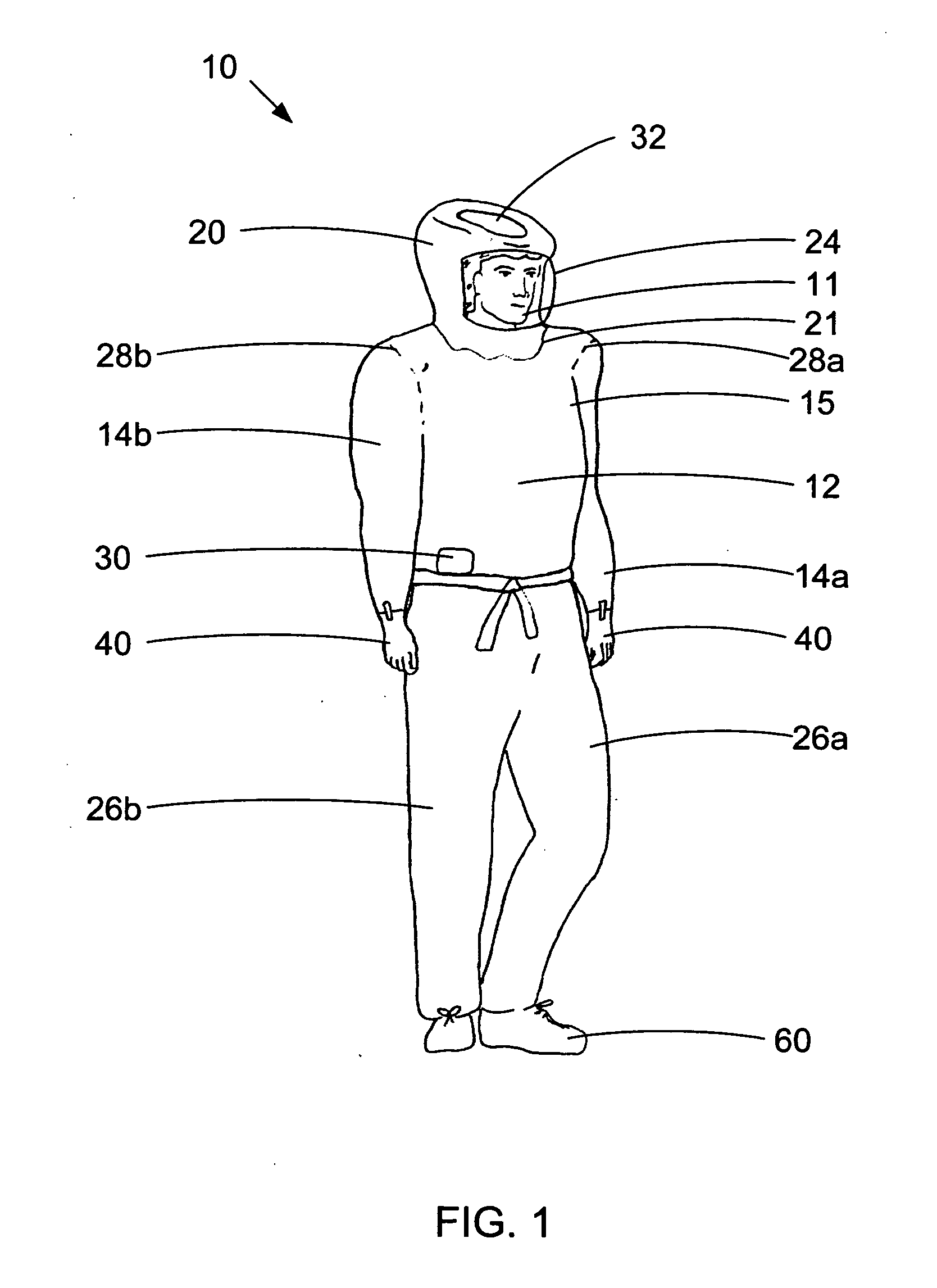
[0043] Protective apparel described herein includes a set of spacers that maintain apparel proximate to the spacers distant from the apparel wearer. FIG. 1 illustrates an outer front elevation view of protective apparel 10 in accordance with one embodiment of the present invention. While the present invention will now be described as protective apparel useful for improving heat managemen...


PUM


Abstract

Described herein is protective apparel that improves management. The protective apparel comprises a set of spacers. Each spacer is arranged on an inner portion of the apparel and maintains apparel proximate to the spacer distant from the person, thereby preventing continuous contact between the person and portions of the apparel. Multiple spacers may form one or more air channel between the spacers, the person and inner portions of the apparel. The channels permit low resistance airflow within the apparel and over the person's body. Low resistance airflow within the channels permits air to be easily moved through the apparel to cool the person. The spacers may comprise a compressible material such as foam. When the compressible material has an elastic memory, elastic return of the material causes each spacer to return to its initial shape after a deforming force is removed. Protective apparel described herein may also comprise a buffer volume of air that allows a person to breath without incurring significant pressure changes internal to the apparel.

Description

CROSS-REFERENCE TO RELATED APPLICATION [0001] This application claims priority under U.S.C. §120 from co-pending U.S. patent application Ser. No. 10 / 887,648, filed Jul. 9, 2004 and entitled, “PROTECTIVE APPAREL SPACERS AND LOW RESISTANCE AIRFLOW”, which is incorporated herein for all purposes and which claimed priority under 35 U.S.C. §119(e) from: a) U.S. Provisional Patent Application No. 60 / 486,274 filed Jul. 10, 2003, b) U.S. Provisional Patent Application No. 60 / 486,150 filed Jul. 10, 2003, c) U.S. Provisional Patent Application No. 60 / 486,232 filed Jul. 10, 2003, d) U.S. Provisional Patent Application No. 60 / 486,225 filed Jul. 10, 2003, e) U.S. Provisional Patent Application No. 60 / 486,151 filed Jul. 10, 2003, f) U.S. Provisional Patent Application No. 60 / 486,155 filed Jul. 10, 2003, and g) U.S. Provisional Patent Application No. 60 / 486,073 filed Jul. 10, 2003, each of these provisional patent applications is incorporated by reference herein for all purposes.BACKGROUND OF THE ...

Claims


Application Information

Patent Timeline
Patent Type & Authority Applications(United States)
IPC IPC(8): A62B17/00A41D13/002A41D13/12A62D5/00
CPCA41D13/002A41D13/12A41D13/1218A41D2400/52A62D5/00
Inventor PLUT, WILLIAM J.
Owner VERASUIT LLC
Why Eureka
Try Eureka