Thermal management matrix

a technology of thermal management matrix and matrix, which is applied in the direction of ceramic layered products, electrochemical generators, chemistry apparatus and processes, etc., can solve the problems of long time-consuming, complex metal system, and many more components, so as to prolong the battery life, improve the performance of li-ion batteries, and reduce the risk of thermal runaway

Inactive Publication Date: 2012-05-03
SGL CARBON SE
View PDF5 Cites 27 Cited by
  • Summary
  • Abstract
  • Description
  • Claims
  • Application Information

AI Technical Summary

Benefits of technology

[0008]What is needed in the art is an enhanced thermal management system to improve Li-ion battery performance, ext...

Problems solved by technology

A disadvantage of the system is that once the PCM/graphite becomes “saturated” with heat, it retains it for a long period of time.
Metal systems (machined, formed, extruded) can be complex, heavy, expensive and require many more components (fittings, fixtures, thermal interf...

Method used


Image

  • Thermal management matrix
  • Thermal management matrix
  • Thermal management matrix

Examples


first embodiment

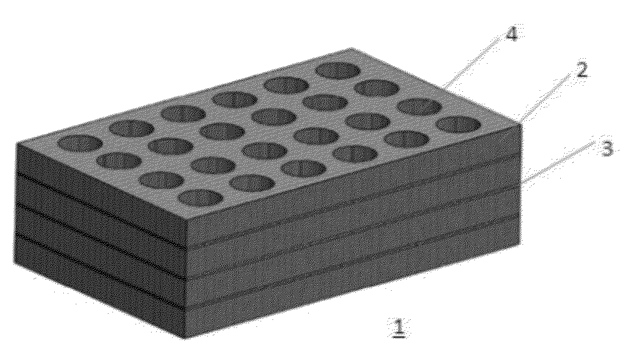
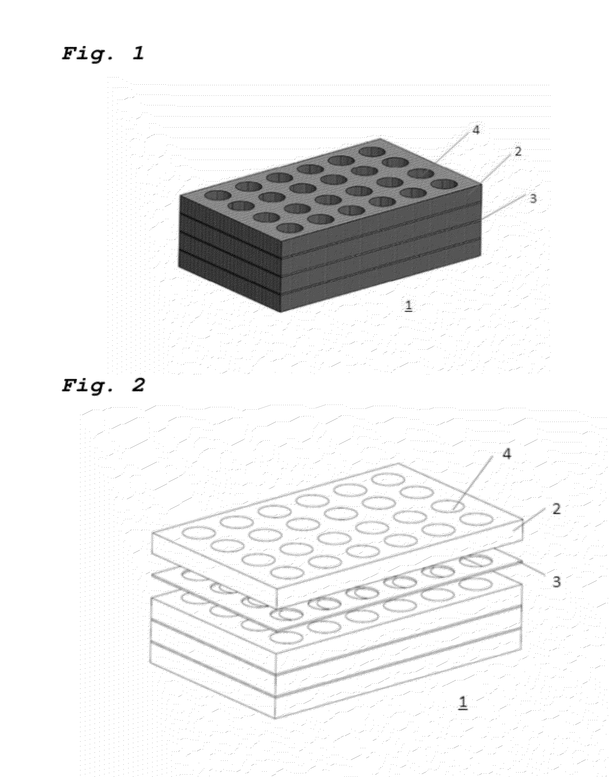
[0046]Referring now to FIG. 1, there is shown the present invention wherein multiple layers of pre-compact expanded graphite are laminated with sheets of graphite foil between them. More specifically, FIG. 1 shows first thermal management matrix 1, including multiple layers 2, 3, that are arranged in a sandwich form. Layers 2 and 3 are formed out of expanded graphite. Layers 2 and 3 have different in-plane thermal conductivities, whereas the in-plane thermal conductivity of layer 3 is higher than the in-plane thermal conductivity of layer 2. The arrangement of the matrix in the form of a sandwich structure shows layer 2 with a lower in-plane thermal conductivity on the top and on the bottom end of the block-like structure. Layers 3 are inserted in between layers 2, neighboring layers 3 with higher in-plane thermal conductivity. The matrix block is provided with openings 4, having a cylindrical size in order to envelope the electrochemical cell elements that may be inserted therein.

[...

second embodiment

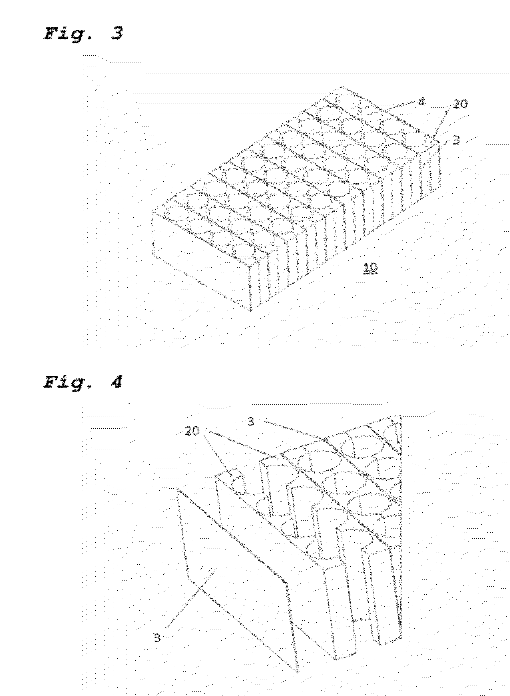
[0051]According to the present invention, molded pieces of pre-compact are used to create a modular design. FIGS. 3 to 5 show different perspective views of this embodiment. Thermal management matrix 10 according to this embodiment of the present invention includes modules 20 and layers 3 with higher density arranged between modules 20. Two modules 20 are arranged facing their grooved side to each other and leaving plane surfaces on the other ends. On these plane surfaces layers 3 in the form of foils are attached. As shown particularly in FIG. 5, grooves 6 are of a semi-cylindrical form and when faced to each other form a cylindrical envelope for electrochemical cell elements.

[0052]In other words, in this embodiment of the present invention, multiple semi-circular grooves 6 equal to approximately one-half the diameter of the Li-ion cells in the stack, are molded into sheets of pre-compact to form one-half of module 20. Thickness can be adjusted by the number of pre-compact layers 2...


PUM

PropertyMeasurementUnit
Densityaaaaaaaaaa
Densityaaaaaaaaaa
Thicknessaaaaaaaaaa

Abstract

A thermal management matrix for an electrochemical cell array including a plurality of electrochemical cell elements, the thermal management matrix at least in part enveloping the electrochemical cell array and being in thermal contact therewith. The thermal management matrix includes mainly expanded graphite, wherein the expanded graphite is arranged in the form of a block-like structure and the block includes at least one layer of expanded graphite having a higher in-plane thermal conductivity than the layers neighboring the layer with higher in-plane thermal conductivity. The thermal management matrix may also include phase change materials as a latent heat storage material.

Description

BACKGROUND OF THE INVENTION[0001]1. Field of the Invention[0002]The present invention relates to a thermal management matrix for an electrochemical cell array including a plurality of electrochemical cell elements, the matrix including layers of expanded graphite with different densities in the form of a sandwich-like structure.[0003]2. Description of the Related Art[0004]The need for thermal management systems to improve Li-ion battery performance, extend battery life and reduce the risks of thermal runaway are well known. Different systems have been developed to address these problems. One present technology differs from the others in that they use PCM (Phase Change Material) infiltrated graphite as a passive solution, to dissipate heat from individual cells in multi-cell modules. This solution is particularly effective where thermal problems are intermittent or “transient”. Other active systems developed for comparison use fluid circulating in metal jackets to dissipate heat and ...

Claims


Application Information

Patent Timeline
IPC IPC(8): H01M10/50B21D53/02
CPCC04B35/536B32B18/00C04B2235/9607C04B2237/363C04B2237/586C04B2237/62C04B2237/64C04B2237/086C04B2237/12C04B2237/72H01M10/652H01M10/6555H01M10/643H01M10/651H01M10/613H01M10/659Y10T29/4935Y02E60/10
Inventor ROMMLER, MIKEFORD, BRIANWENDEL, STEVEKRULL, TIM
Owner SGL CARBON SE
Why Eureka
Try Eureka