Thrust vector control

a technology of thrust control and thrust vector, applied in the direction of machines/engines, marine propulsion, vessel construction, etc., can solve the problems of complex control mechanisms, heavy and expensive thrust control systems for changing the flow path of convergent-diverse fluid, and fluidic nozzles that require expensive piping systems

Inactive Publication Date: 2006-07-13
HONEYWELL INT INC
View PDF34 Cites 30 Cited by
  • Summary
  • Abstract
  • Description
  • Claims
  • Application Information

AI Technical Summary

Benefits of technology

[0008] In one aspect of the present invention, a thrust vector control system comprises a fixed nozzle; and at least one exhaust deflector adapted for movement to a location downstream of the fixed nozzle, wherein the movement comprises translational motion, and the movement of each exhaust deflector is independently controllable.

Problems solved by technology

Prior art thrust control systems for changing the nozzle convergent-divergent flow path are heavy and expensive, and require complex control mechanisms.
Such fluidic nozzles require expensive piping systems to inject the bleed air into the nozzle exhaust gas flow.
In addition, such fluidic designs are inefficient, difficult to control, and particularly unsuitable for low engine power applications, such as idle conditions.

Method used


Image

  • Thrust vector control
  • Thrust vector control
  • Thrust vector control

Examples


Embodiment Construction

[0028] The following detailed description is of the best currently contemplated modes of carrying out the invention. The description is not to be taken in a limiting sense, but is made merely for the purpose of illustrating the general principles of the invention, since the scope of the invention is best defined by the appended claims.

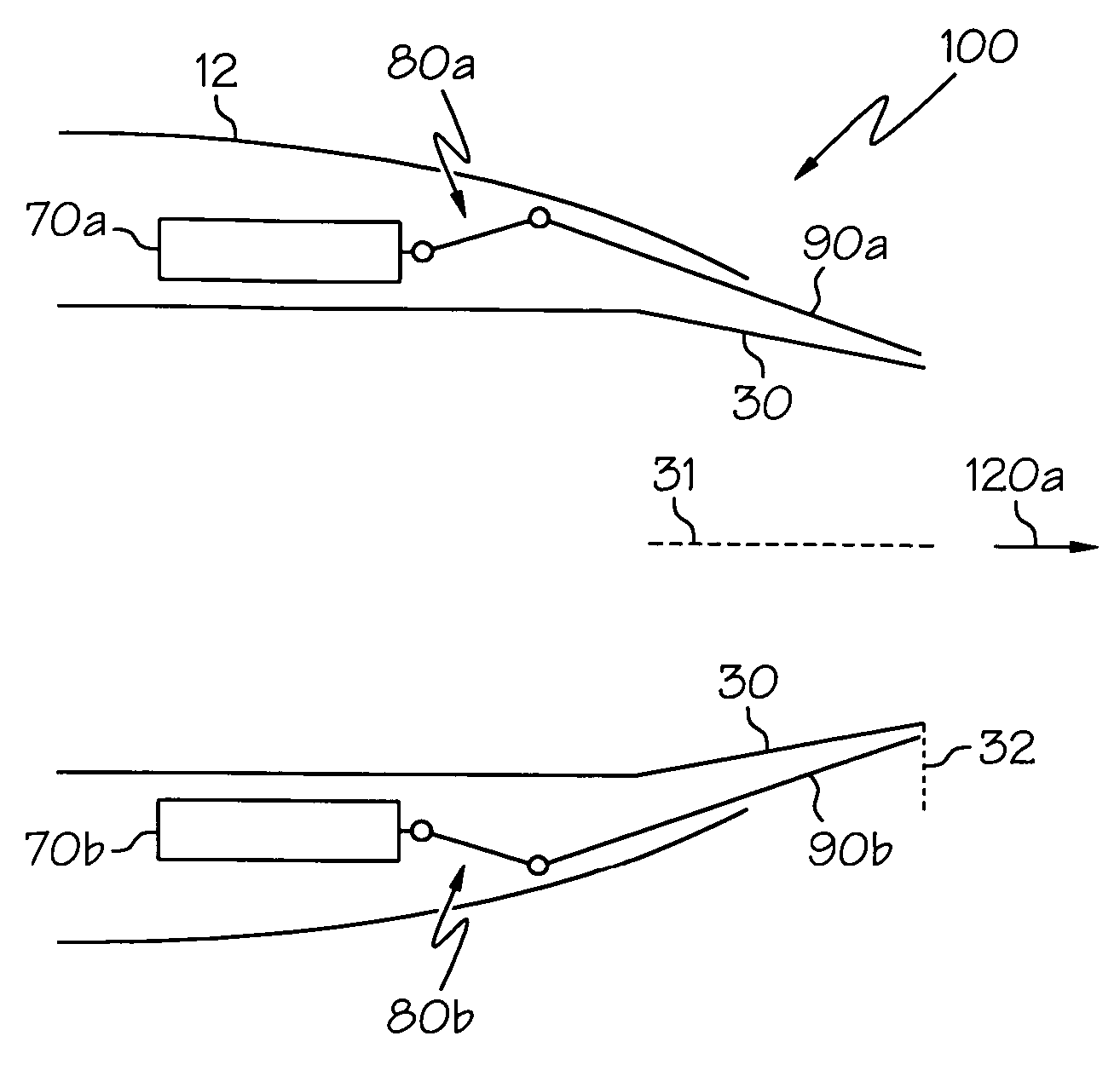
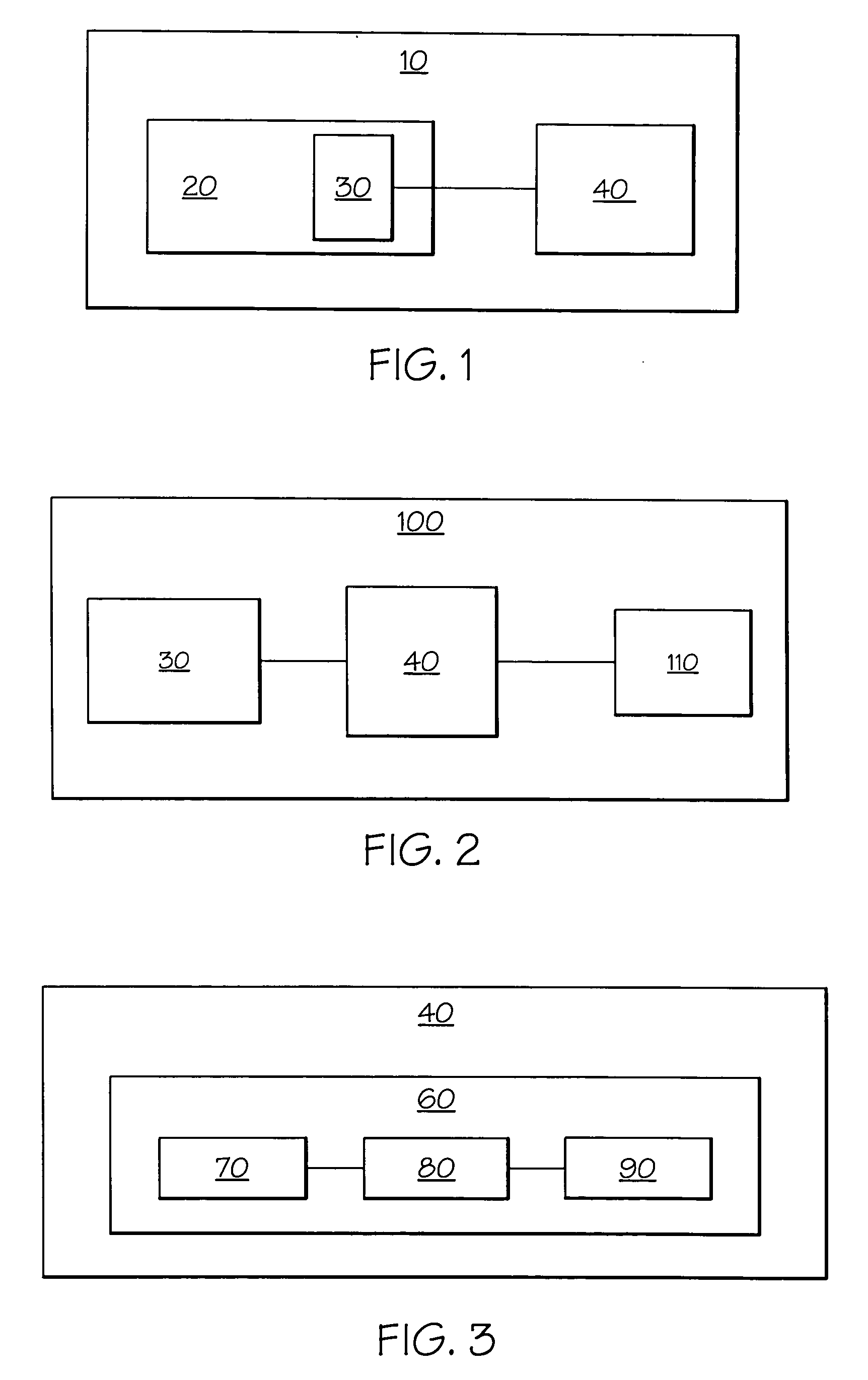
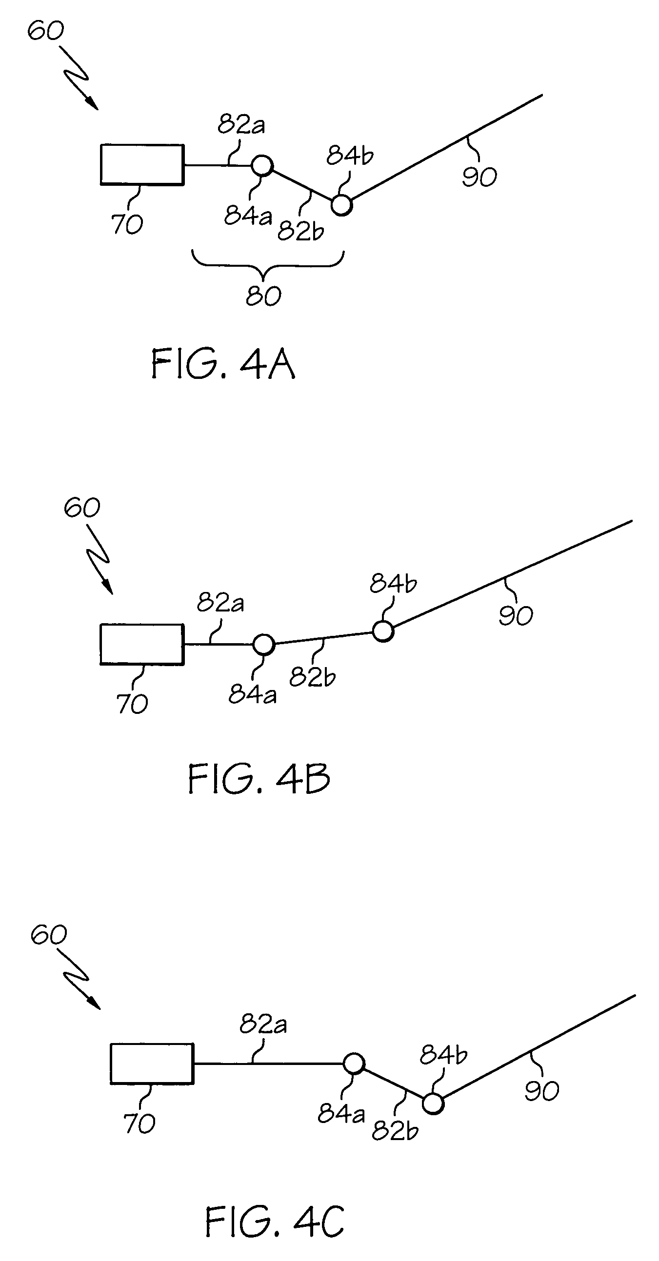
[0029] Broadly, the present invention provides apparatus and methods for thrust vector control of a nozzle of a flight vehicle. The present invention may be used to change, or control, the thrust vector direction of, for example, a gas turbine engine. The present invention may also allow for simultaneous control of nozzle throat area and thrust vector direction. The present invention may be used for flight control of aircraft, including rotorcraft and fixed-wing aircraft, as well as rocket-propelled space vehicles, missiles, and the like. The present invention may also be used for flight control of tailless flight vehicles and unmanned flight vehicles...


PUM


Abstract

A thrust vector control system for a flight vehicle comprises a fixed nozzle defining a first thrust vector direction and at least one exhaust deflector moveable to a location downstream of said fixed nozzle to provide a second thrust vector direction. Movement of the at least one exhaust deflector may allow for simultaneous control of both thrust vector direction and nozzle throat area. Translational motion of each exhaust deflector may be independently controlled. A flight vehicle incorporating a thrust vector control apparatus, and a method for thrust vector control are also disclosed.

Description

BACKGROUND OF THE INVENTION [0001] The present invention relates generally to apparatus and methods for thrust vector control, and more particularly to thrust vector control for a gas turbine engine of a flight vehicle. [0002] Gas turbine engines for modern military and commercial aircraft use exhaust nozzles to control engine exhaust expansion and velocity distribution. By controlling engine exhaust expansion and velocity distribution, the engine exhaust nozzle provides relatively high thrust efficiency. [0003] Conventional control of the discharge of the heated exhaust gas from a gas turbine engine may be achieved by varying the throat area of the nozzle. The throat area is defined as the minimum area through which the heated gas must pass to be discharged from the nozzle exit. For a convergent nozzle, the nozzle throat is typically the nozzle exit. [0004] Prior art mechanisms for throat area control of an exhaust nozzle of a gas turbine engine are disclosed, for example, in U.S. ...

Claims


Application Information

Patent Timeline
Patent Type & Authority Applications(United States)
IPC IPC(8): F02K1/00
CPCF02K1/002F02K1/08F02K1/1207F02K1/763
Inventor ANDERSON, MORRIS G.JOHNSTON, MARKKNAUER, CHAD E.
Owner HONEYWELL INT INC
Why Eureka
Try Eureka