Apparatus for cutting substrate and method thereof

a technology of substrate and apparatus, applied in the direction of paper/cardboard containers, manufacturing tools, instruments, etc., can solve the problems of difficult to completely remove the coolant after dicing, high probability of metal parts corroding, and the dicing method is not suitable for a flat panel display including metal parts, so as to prevent vibration and enhance productivity.

Active Publication Date: 2006-07-13
LG DISPLAY CO LTD
View PDF6 Cites 12 Cited by
  • Summary
  • Abstract
  • Description
  • Claims
  • Application Information

AI Technical Summary

Benefits of technology

[0031] An object of the present invention is to provide an apparatus for cutting a substrate and method thereof that prevent against vibration of belt conveyers and conveyer support beams to enhance productivity.

Problems solved by technology

However, since a frictional heat is generated at a zone that is being cut by the blade, the blade cutting is carried out by supplying a coolant or cooling water to the corresponding zone and it is difficult to completely remove the coolant after completion of dicing.
Thus, if moisture remains due to the incomplete removal of the cooling water, it is highly probable that any metal parts will corrode.
Thus, the dicing method is not suitable for a flat panel display including metal parts, such as a metal electrode layer, a metal terminal and the like.
In addition, a cutting time of the dicing method is longer than that of the scribing method, thereby lowering productivity.
When the liquid crystal molecules are injected in the LCD panel, air amongst the liquid crystal molecules creates bubbles within the LCD panel that cause device failure.
First, vibration is generated from the scribing process or the guide rails.
Hence, it is unable to carry out the scribing process on a next substrate smoothly.
In addition, in the X-axis scribe of the related art, the scribe damage is not formed to the uniform depth due to the belt interval and shaking by the conveyer support beam arranged in the Y-axis direction.
Such a damage depth is further varied due to unevenness of the belt conveyer.
Further, the conveyer support beam and the beam support bar frame are deformed due to the vibration that twists the conveyer leveling.

Method used


Image

  • Apparatus for cutting substrate and method thereof
  • Apparatus for cutting substrate and method thereof
  • Apparatus for cutting substrate and method thereof

Examples


Embodiment Construction

[0044] Reference will now be made in detail to the preferred embodiments of the present invention, examples of which are illustrated in the accompanying drawings.

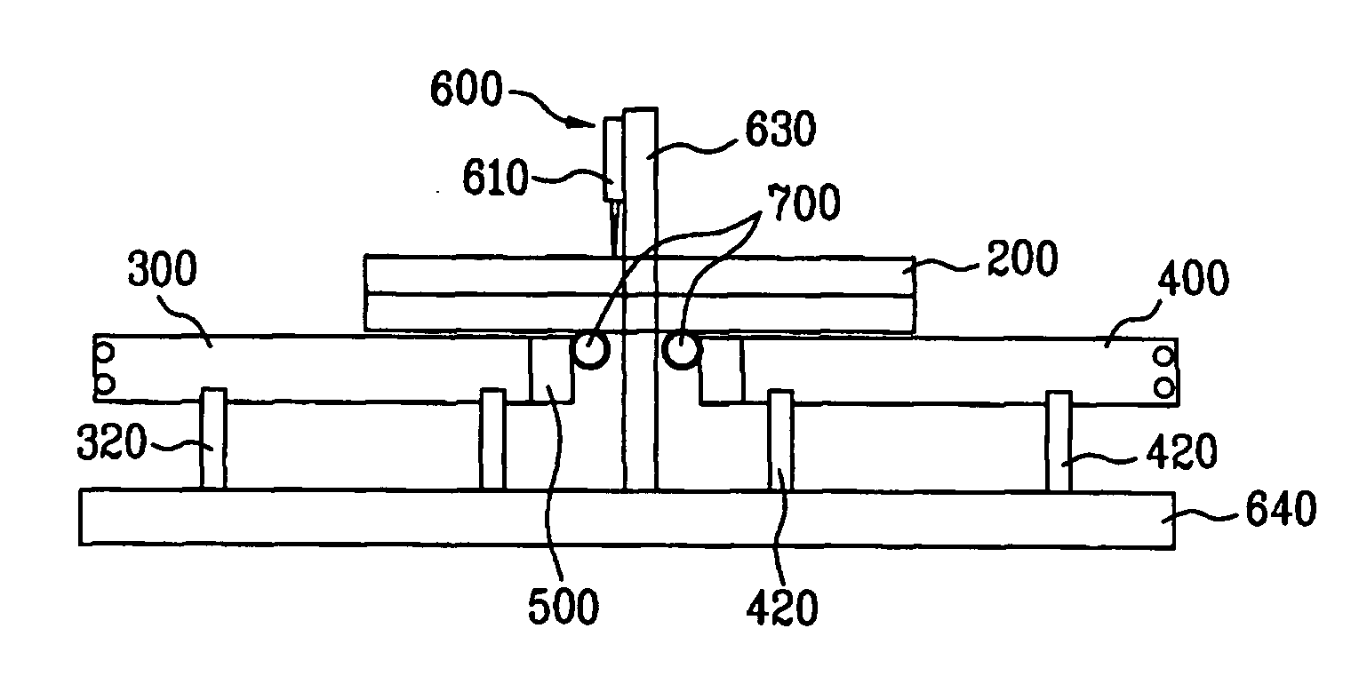
[0045]FIG. 4A is a cross-sectional diagram illustrating an exemplary substrate cutting apparatus according to an embodiment of the present invention, and FIG. 4B is a plane view illustrating the substrate cutting apparatus shown in FIG. 4A. Referring to FIG. 4A and FIG. 4B, a substrate cutting apparatus includes first and second belt conveyers 300 and 400 arranged with a predetermined distance spaced apart from each other to load and convey a mother substrate 200 to be cut. For example, the first and second belt conveyers 300 and 400 may be spaced apart from each other by about 15 cm. The substrate cutting apparatus also includes driving units 500 provided at ends of the first and second belt conveyers 300 and 400 to drive the first and second belt conveyers 300 and 400, respectively, a scriber 600 provided between the fir...


PUM

PropertyMeasurementUnit
thickaaaaaaaaaa
thickaaaaaaaaaa
shapeaaaaaaaaaa

Abstract

An apparatus for cutting a substrate includes first and second belt conveyers for conveying the substrate thereon, a scriber for scribing the substrate along a cutting-reserved line, the scriber provided between the first and second belt conveyers and being spaced apart from the first and second belt conveyers, and a substrate support for securing the substrate, the substrate support provided between the first and second belt conveyers along a scribing direction of the substrate.

Description

[0001] The present invention claims the benefit of Korean Patent Application No. P2004-112867 filed in Korea on Dec. 27, 2004, which is hereby incorporated by reference. BACKGROUND OF THE INVENTION [0002] 1. Field of the Invention [0003] The present invention relates to a liquid crystal display device and, more particularly, an apparatus for cutting a substrate and method thereof. Although the present invention is suitable for a wide scope of applications, it is particularly suitable for cutting a liquid crystal display mother substrate. [0004] 2. Discussion of the Related Art [0005] Since the information communication field is developing rapidly, display devices for disposing and displaying information are actively being developed. A cathode ray tube (CRT) has been popular as an information display due to its excellent screen brightness and capability of displaying various colors. However, as the demand for wide-screen, portability and high resolution rises, many recent efforts hav...

Claims


Application Information

Patent Timeline
Patent Type & Authority Applications(United States)
IPC IPC(8): B26D1/00
CPCB28D5/0011B28D5/0082B65G2249/04C03B33/03C03B33/033C03B33/07G02F1/133351Y02P40/57Y10T225/325Y10T225/12Y10T83/0385Y10T83/0333Y10T83/04G02F1/13
Inventor KIM, JUNG SIK
Owner LG DISPLAY CO LTD
Why Eureka
Try Eureka