Pickup apparatus

a technology of picking up apparatus and pickup, which is applied in the direction of instruments, electrophonic musical instruments, etc., can solve the problems of inability to accurately detect the pitch and amplitude of each string, the output of the pickup b>21/b> is mixed, and it is not possible to accurately detect the pitch and amplitude of the vibration of each string. it is possible to prevent crosstalk, reduce the effect of a change in the magnetic force line of one pickup on th

Inactive Publication Date: 2006-07-13
ROLAND CORP
View PDF6 Cites 21 Cited by
  • Summary
  • Abstract
  • Description
  • Claims
  • Application Information

AI Technical Summary

Benefits of technology

[0019] In the first preferred embodiment, the pickup is a humbucking type pickup with two magnetic poles on the side that faces the string, and the direction that the two magnetic poles face other each forms an angle of at least 20 degrees with respect to the length direction of the strings, and that adjacent pickups are arranged having the angle that the two magnetic poles face mutually reciprocal to the length direction of the strings. As a result, the direction of the magnetic force lines formed by the two magnetic poles, the N pole and the S pole, is at an angle at least 40 degrees with respect to the direction of the magnetic force lines of the adjacent pickup. Therefore, there is the advantageous result that a change in the magnetic force lines due to the vibration of the one string will have minimal effect on the adjacent pickup, and it is possible to prevent crosstalk.
[0020] A pickup apparatus in the second preferred embodiment is arranged such that the adjacent pickups are positioned different to each other along t...

Problems solved by technology

Accordingly, when crosstalk is produced, it is not possible to accurately detect the pitch and amplitude of each string.
In addition, there is the problem that in those cases where both string...

Method used


Image

  • Pickup apparatus
  • Pickup apparatus
  • Pickup apparatus

Examples


Embodiment Construction

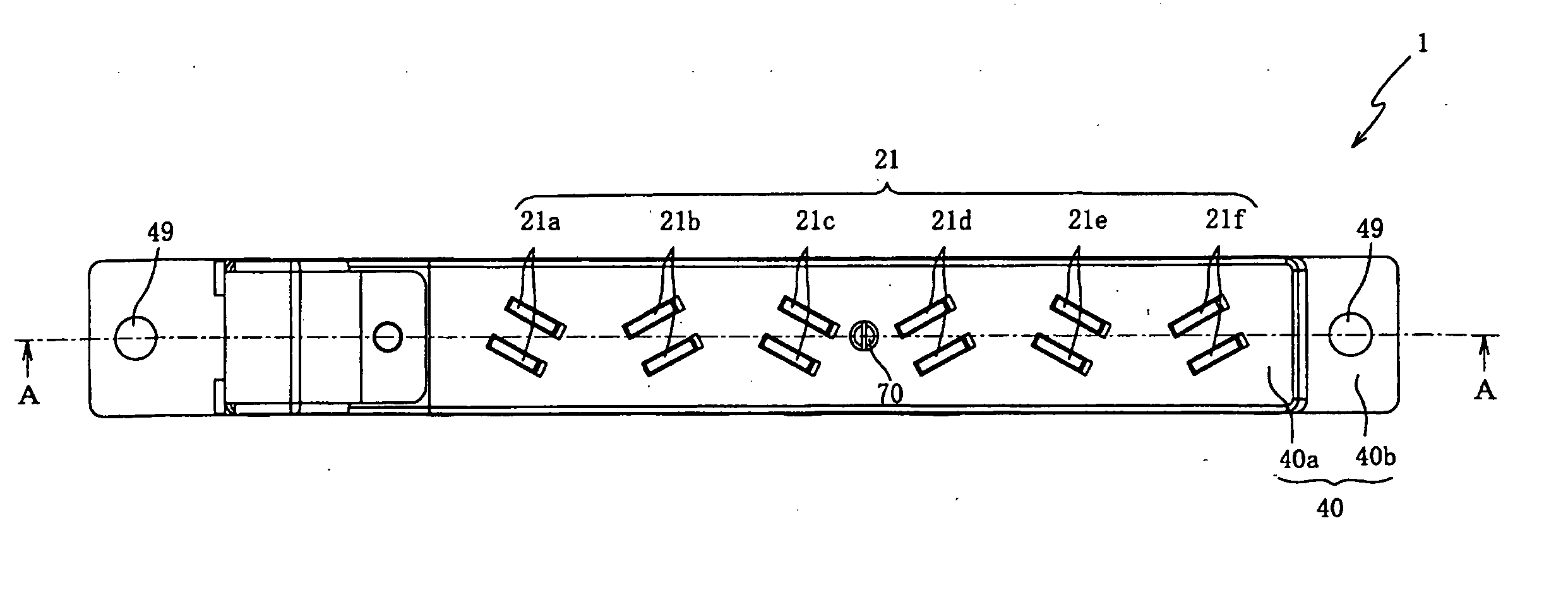
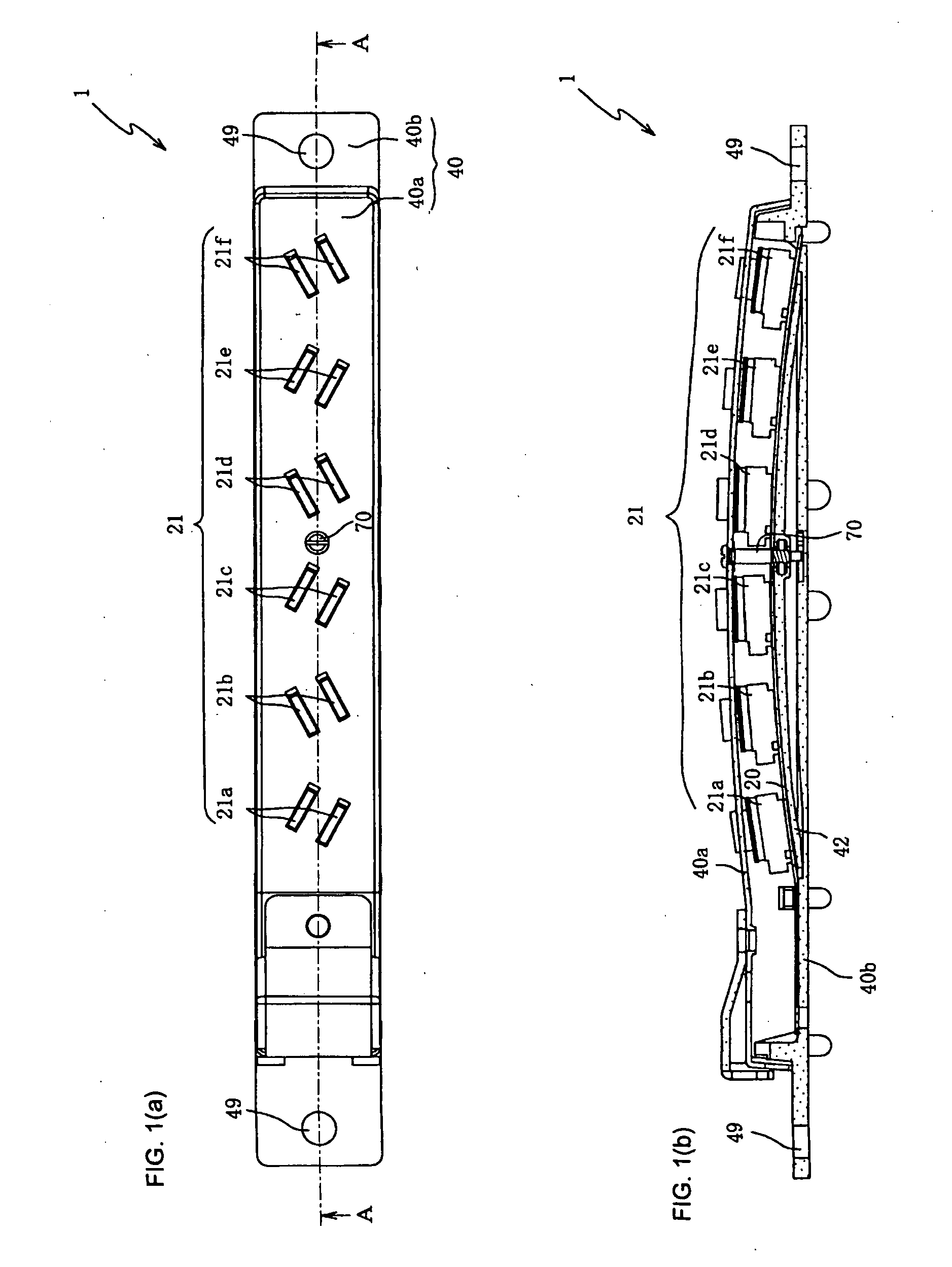
[0028] An explanation will be given below regarding a first preferred embodiment of the present invention while referring to the attached drawings. FIG. 1(a) is an external planar drawing of a pickup apparatus 1, and FIG. 1(b) is a cross-section drawing along the line A-A of FIG. 1(a). An explanation of the pickup apparatus 50 was given above, hence the explanations relating to portions with the same keys as described above for the pickup apparatus 50 are omitted. An explanation will only be given regarding the portions of the pickup apparatus 1 that are different from the pickup apparatus 50.

[0029] In the pickup apparatus 1, six pickups 21a through 21f are mounted on the pickup board 20, and the pickup board 20 is fastened by a leaf spring 42 housed inside the top case 40a. The top case 40a and the bottom case 40b comprise the case 40.

[0030] An adjusting screw 70 that adjusts the curvature of the leaf spring 42 is positioned roughly in the center of the pickup apparatus 1 along t...


PUM


Abstract

A pickup apparatus for independently detecting the vibrations of each of a plurality of strings, and an electronic stringed instrument utilizing the pickup apparatus. The pickup apparatus minimizes the crosstalk effects between the different pickups by positioning the pickups such that the magnetic force lines of each pickup is not parallel to or not in close proximity of the magnetic force lines of adjacent pickups. In one example, each pickup in the pickup apparatus is disposed at an angle with respect to the string and with respect to adjacent pickups. In another example, each pickup is disposed at an offset along the length direction of the strings relative to adjacent pickups. In yet another example, each pickup is disposed both at an angle and at an offset relative to adjacent pickups.

Description

CROSS-REFERENCE TO RELATED PATENT APPLICATIONS [0001] This application claims priority to Japanese patent application No. 2005-002001 (filed on Jan. 7, 2005 in Japan), which was assigned to the applicant and is incorporated herein by reference, in its entirety. BACKGROUND OF THE INVENTION [0002] Embodiments of the present invention relate generally to a pickup apparatus that independently detects the vibrations of a plurality of strings in a stringed instrument, a stringed instrument utilizing such a pickup apparatus and a method of arranging pickups on a stringed instrument. [0003] For some time, pickup apparatuses that are used in guitar synthesizers have been formed such that the vibrations of each of the strings of the electric guitar are independently detected. FIG. 4 is a drawing that shows a portion of an electric guitar 100 on which a pickup apparatus 50 for a guitar synthesizer has been mounted. [0004] As shown in FIG. 4, the pickup apparatus 50 has six pickups 21 (21a-21f)...

Claims


Application Information

Patent Timeline
IPC IPC(8): G10H3/18
CPCG10H3/182G10H2220/505G10H2220/565
Inventor HARA, KOJI
Owner ROLAND CORP
Why Eureka
Try Eureka