Impact wrench anvil and method of forming an impact wrench anvil

a technology of impact wrenches and anvils, which is applied in the field of impact wrenches, can solve the problems of loose fit to the square portion of the anvil, increased stress zones, and inefficiencies in design, and achieve the effect of eliminating sharp corners and small radii

Inactive Publication Date: 2006-07-13
BLACK & DECKER INC
View PDF27 Cites 24 Cited by
  • Summary
  • Abstract
  • Description
  • Claims
  • Application Information

AI Technical Summary

Problems solved by technology

These sharp corners or small radii may create some inefficiencies in the design.
However, the impact socket may, over a long period of use, become “damaged”, resulting in a looser fit to the square portion of the anvil.
These points of contact form at the sharp radii in the transition between the round body and the square drive and lead to zones of increased stress.
Moreover, as the impact socket becomes “damaged”, the corners of the impact socket tend to “dig” into the sharp radii in the transition.
This digging between the impact socket and the square portion can damage the anvil, resulting in stress concentration zones.
As the stress builds at these points, the anvil may fail at the stress concentration zones.
This then can contribute to an early failure of the anvil.
Unfortunately, this alloying leads to increases in the amount of retained austenite within the anvil.
The retained austenite inhibits strength for impact loading and often leads to fatigue failures.

Method used


Image

  • Impact wrench anvil and method of forming an impact wrench anvil
  • Impact wrench anvil and method of forming an impact wrench anvil
  • Impact wrench anvil and method of forming an impact wrench anvil

Examples


Embodiment Construction

[0013] The following description of the preferred embodiment is merely exemplary in nature and is in no way intended to limit the invention, its application, or uses.

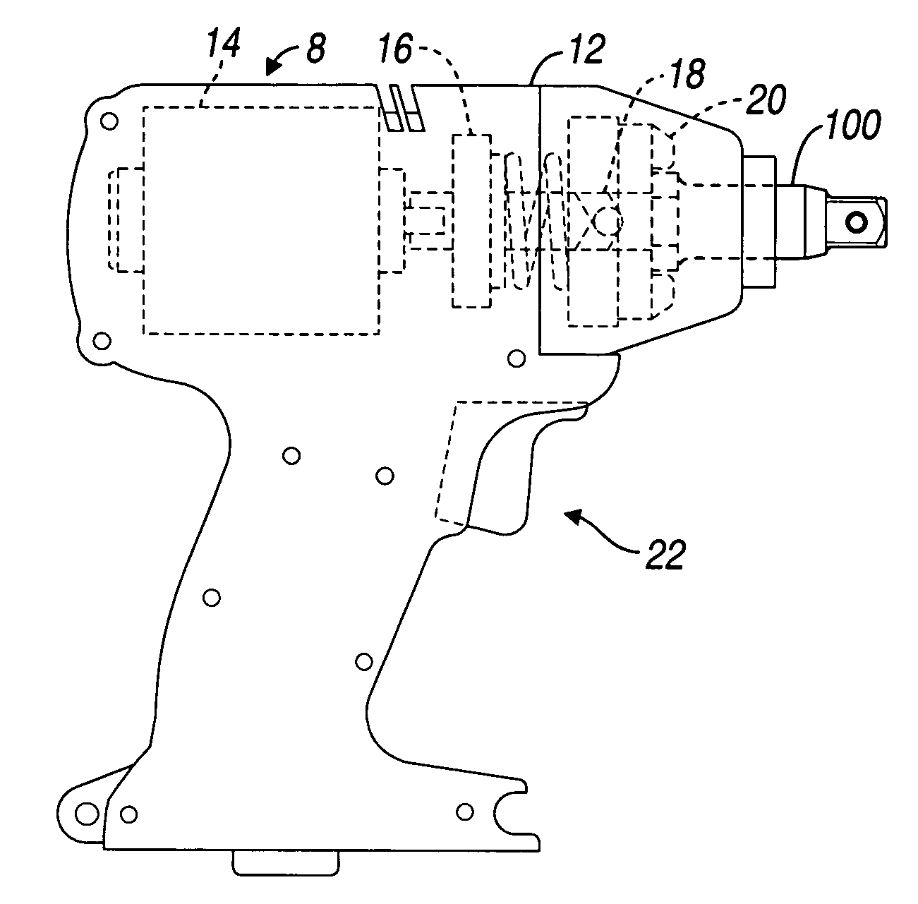
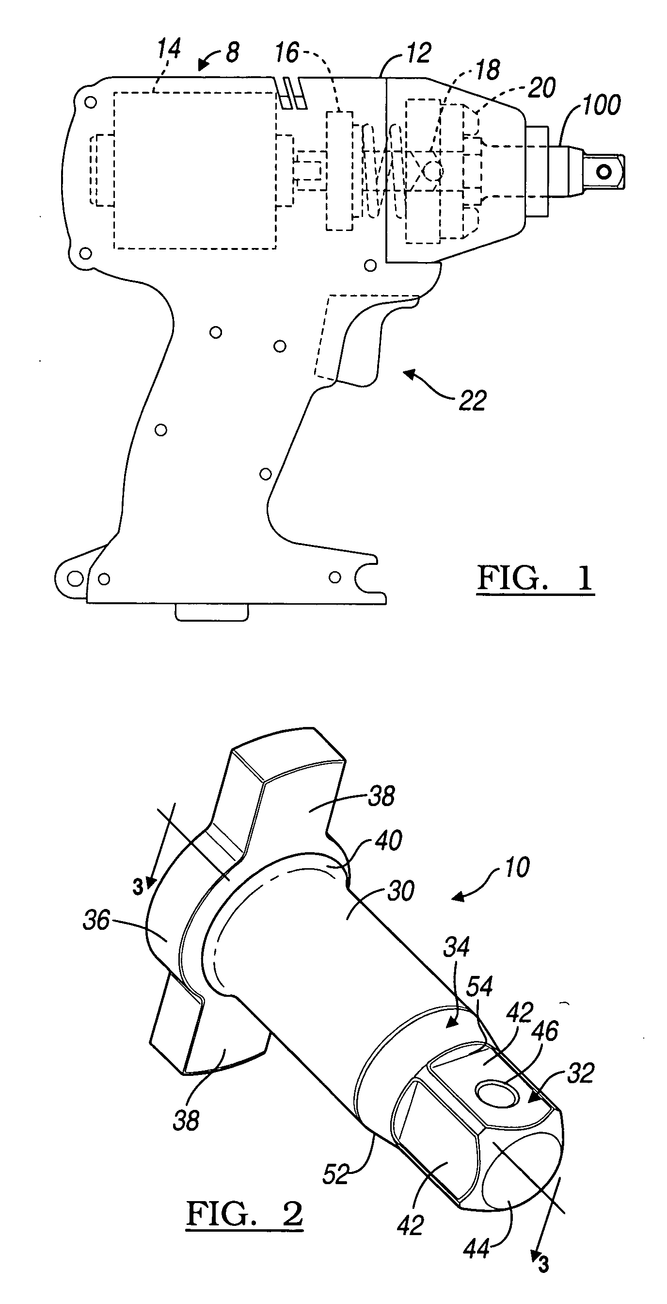
[0014] With reference to FIG. 1 of the drawings, an exemplary impact wrench 8 is illustrated to include an improved anvil100 that is constructed in accordance with the teachings of the present invention. The impact wrench 8 also includes a housing 12 containing an electric motor 14 whose output is coupled to a gear assembly 16. The gear assembly 16 transfers the output to a cam shaft 18 which in turn drives an impactor 20. The improved anvil 100 is mounted within the impactor 20. A trigger and handle assembly 22 mounted to the housing 12 is used to activate the electric motor 14.

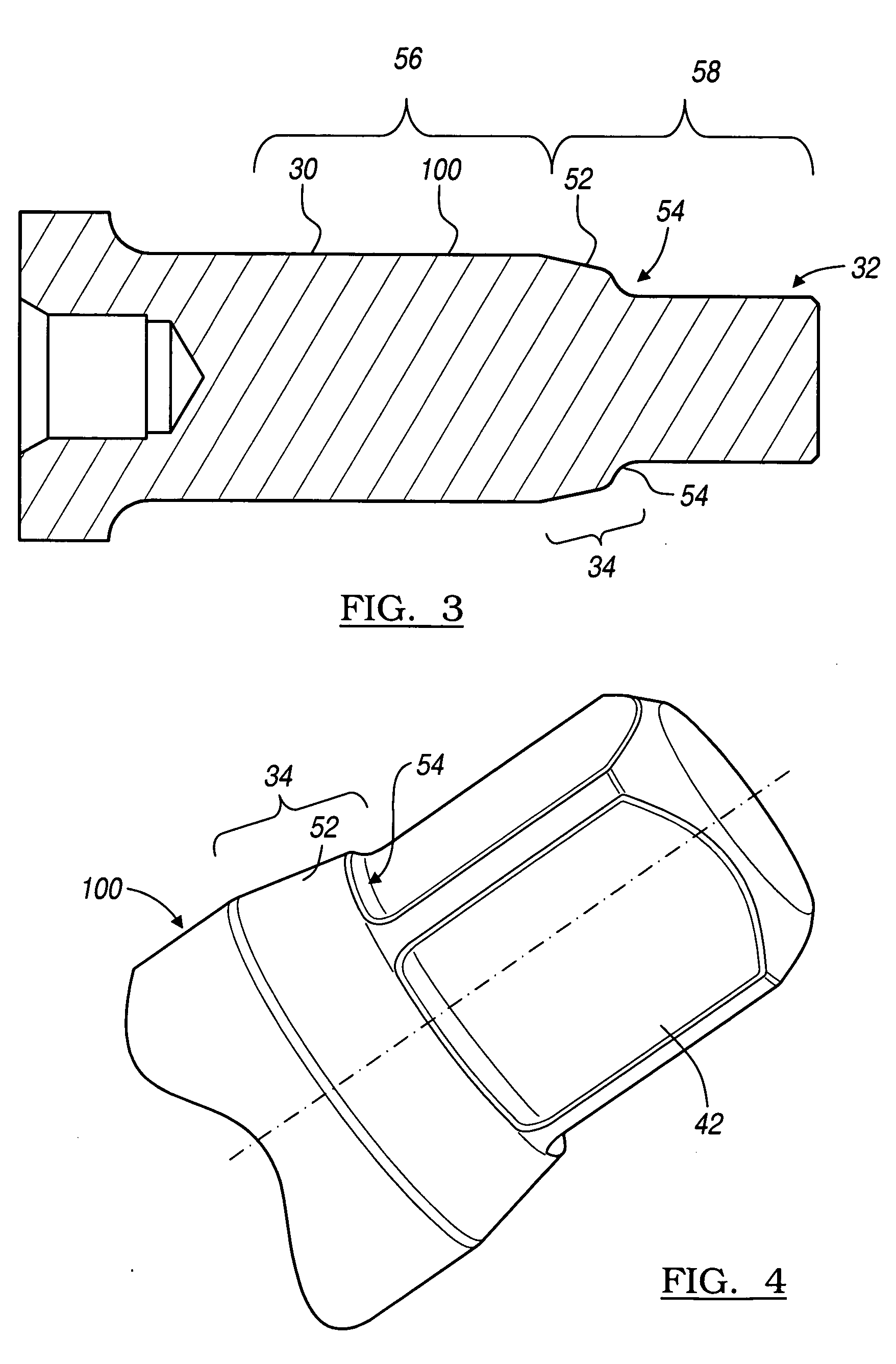
[0015] The round body 30 is generally cylindrical in shape and includes an enlarged base 36 at one end thereof. The enlarged base 36 includes two locking wings 38 extending therefrom and adapted to be received within the impactor 20. A base ra...


PUM

PropertyMeasurementUnit
temperaturesaaaaaaaaaa
exterior radiusaaaaaaaaaa

Abstract

An anvil adapted to be received within an impact wrench comprises a round body and a square head. The square head is formed at an end of the round body. A tapered ramp extends from the round body to the square head. A radius is formed in the tapered ramp.

Description

FIELD OF THE INVENTION [0001] The present invention relates to an impact wrench and more particularly to an improved anvil in an impact wrench. BACKGROUND OF THE INVENTION [0002] The traditional design of an anvil for use in an impact wrench includes a round portion that transitions to a square portion. The round portion is received within the impact wrench and acts as a bearing journal. The square portion is received within an impact socket. The transition from the round cross section to the square cross section inherently creates sharp corners or small radii within the transition. [0003] These sharp corners or small radii may create some inefficiencies in the design. Initially there is minimal clearance between the square portion of the anvil and the impact socket when the pieces are new. However, the impact socket may, over a long period of use, become “damaged”, resulting in a looser fit to the square portion of the anvil. This increased clearance between the square portion inte...

Claims


Application Information

Patent Timeline
Patent Type & Authority Applications(United States)
IPC IPC(8): B25D11/00
CPCB25B21/02Y10T29/49B25B23/0035
Inventor BODINE, THOMAS J.BRUNER, DAVID S.PARIS, ALAN M.
Owner BLACK & DECKER INC
Why Eureka
Try Eureka