[0016] A particular objective of the invention is to obtain a
cell concentrate from
whole blood (including
umbilical cord blood),
bone marrow aspirate, or other
physiological fluid in an efficient fashion through
centrifugation and the expressing of the several components. The
cell concentrate preferably includes the
buffy coat, some red cells, and
plasma in desired ratio. The
buffy coat is a
thin layer that forms during
centrifugation and includes mostly all of the cells other than the red blood cells. The buffy coat is known to include platelets, white cells, nucleated cells, and stem sells cells and may include other components as well. Because the buffy coat is a somewhat diffuse layer that is easily disrupted and mixed with the other components, which reduces the effectiveness of the procedure, an object of the invention is to provide a container that can be operated to dispense the
cell concentrate without significant mixing of the desired cells with the
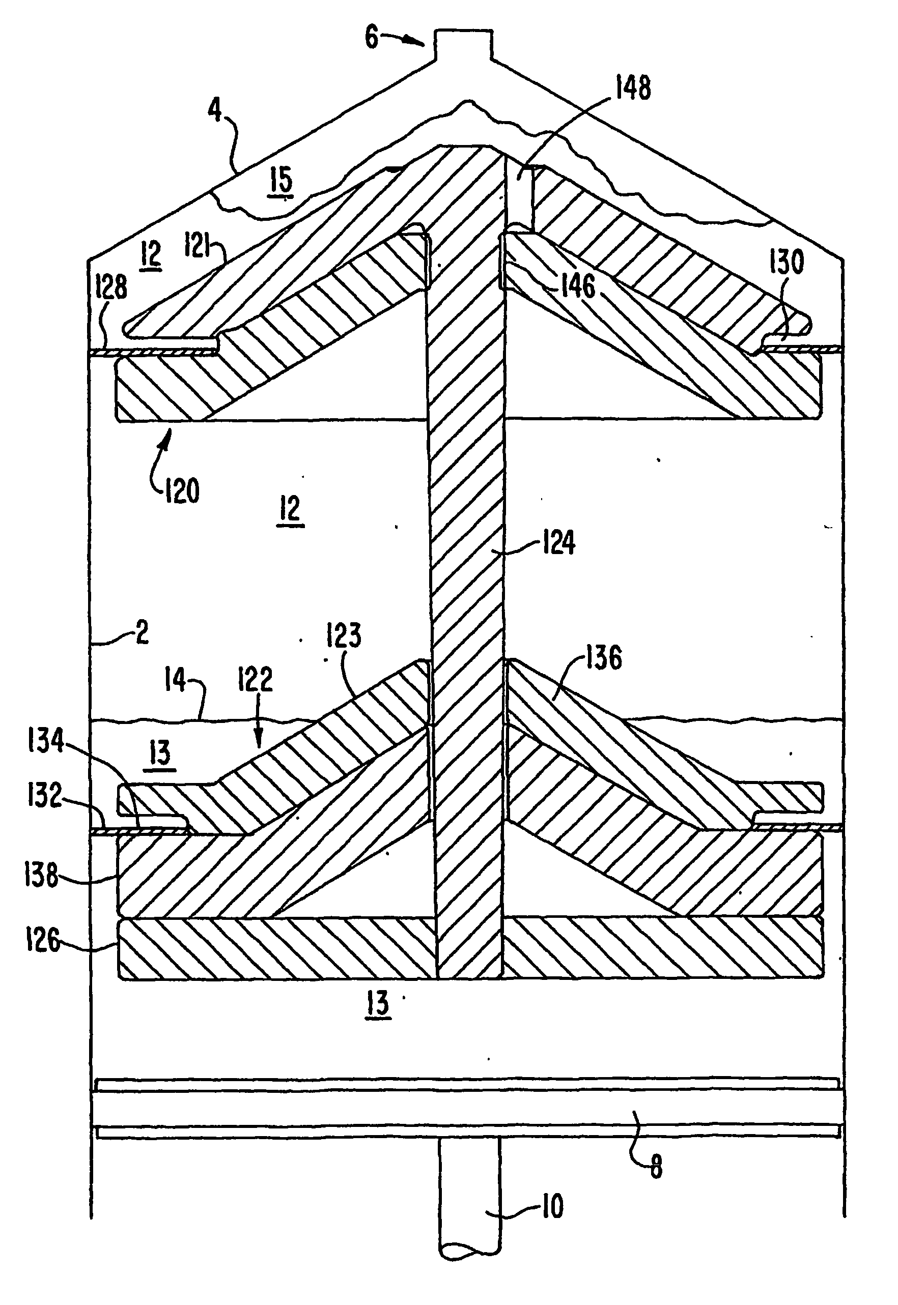
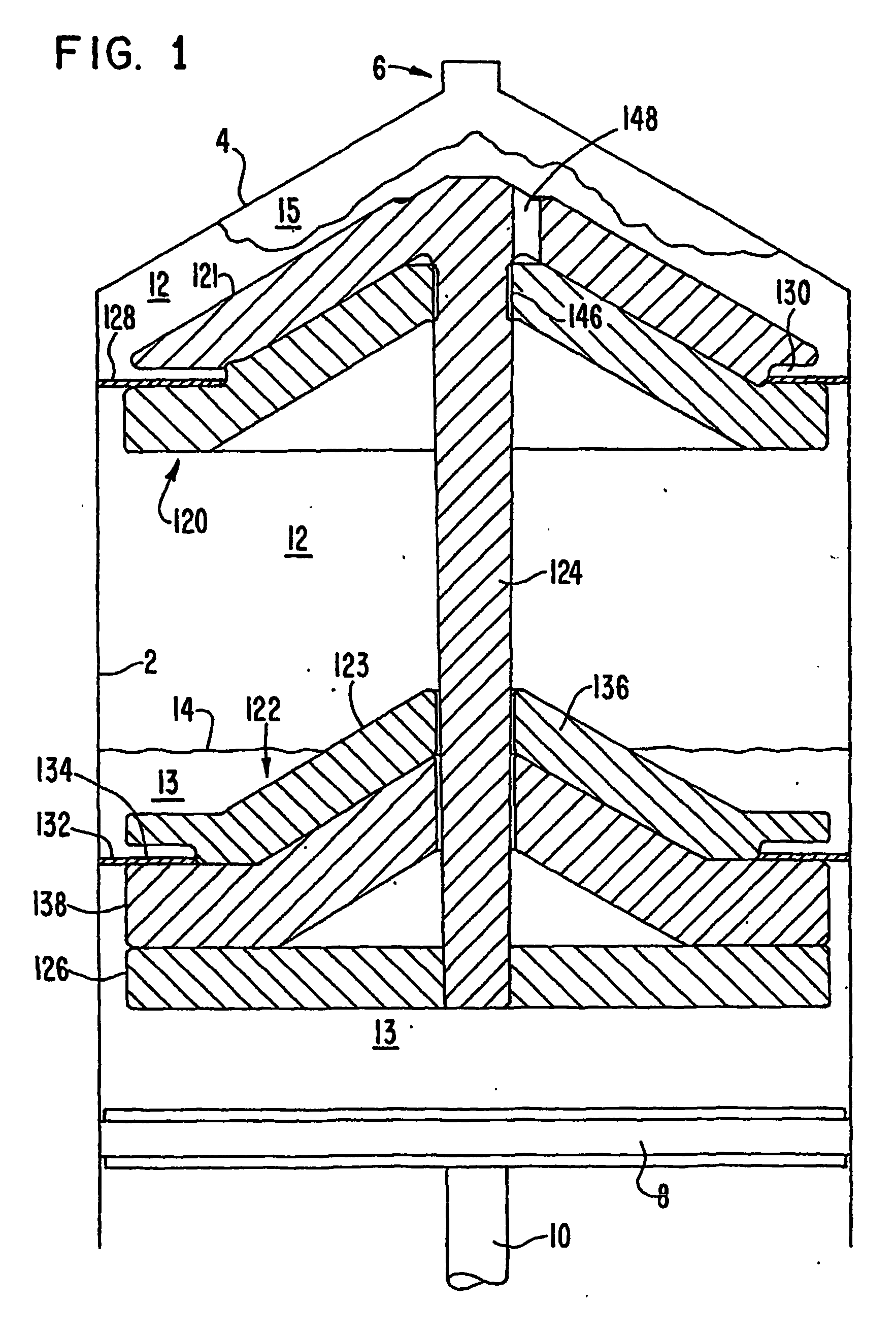
plasma or the red blood cells. This is accomplished in the preferred embodiments primarily by providing a flow path for the cell concentrate that reduces mixing between the components. In the preferred embodiments, a disk
assembly floats in a region containing an interface between plasma and the buffy coat and a diffuse interface between the buffy coat and the red cells, and assists in separating those components. As well, the disk
assembly is shaped so that it forms a flow path for the components and reduces turbulence during separation of the components to prevent mixing the components during their expression.
[0017] In its preferred embodiment, a disk
assembly that is allowed to float in the fluid presents a
vertical gradient in the buoyant forces that cause it to assume a position in the region having the desired component, e.g., the buffy coat. This gradient is provided either by the shape of the assembly, by the use of materials of different densities, or by a combination of both. In the preferred embodiment, the disk assembly provides a conical upper surface, and an upper portion of the assembly is made of a material that is less dense than red blood cells but more dense that plasma. A lower portion of the assembly is made of a material that is denser than the red blood cells. Because of the conical shape, the
buoyant force provided by the upper element at the boundary between the plasma and the red blood cells and in the region of the buffy coat is a non-linear function of the distance by which the upper element extends into the plasma. The
density gradient of the fluids in the
boundary region is large, and the use of a floating element with a
density gradient also has been found to be beneficial.
[0018] The disk assembly according to the invention is designed to encompass both a desired component and a predetermined volume of fluid surrounding the desired component. In the preferred embodiment, the disk assembly comprises two floating parts that are movable relative to each other whereby the entire assembly is caused to assume a desired position after centrifugation, and one part moves toward the other during expression of the fluids to express a desired component or components, e.g., the buffy coat and a predetermined volume of plasma. This structure allows the user to obtain a cell concentrate comprising the buffy coat mixed with plasma at a desired increased concentration.
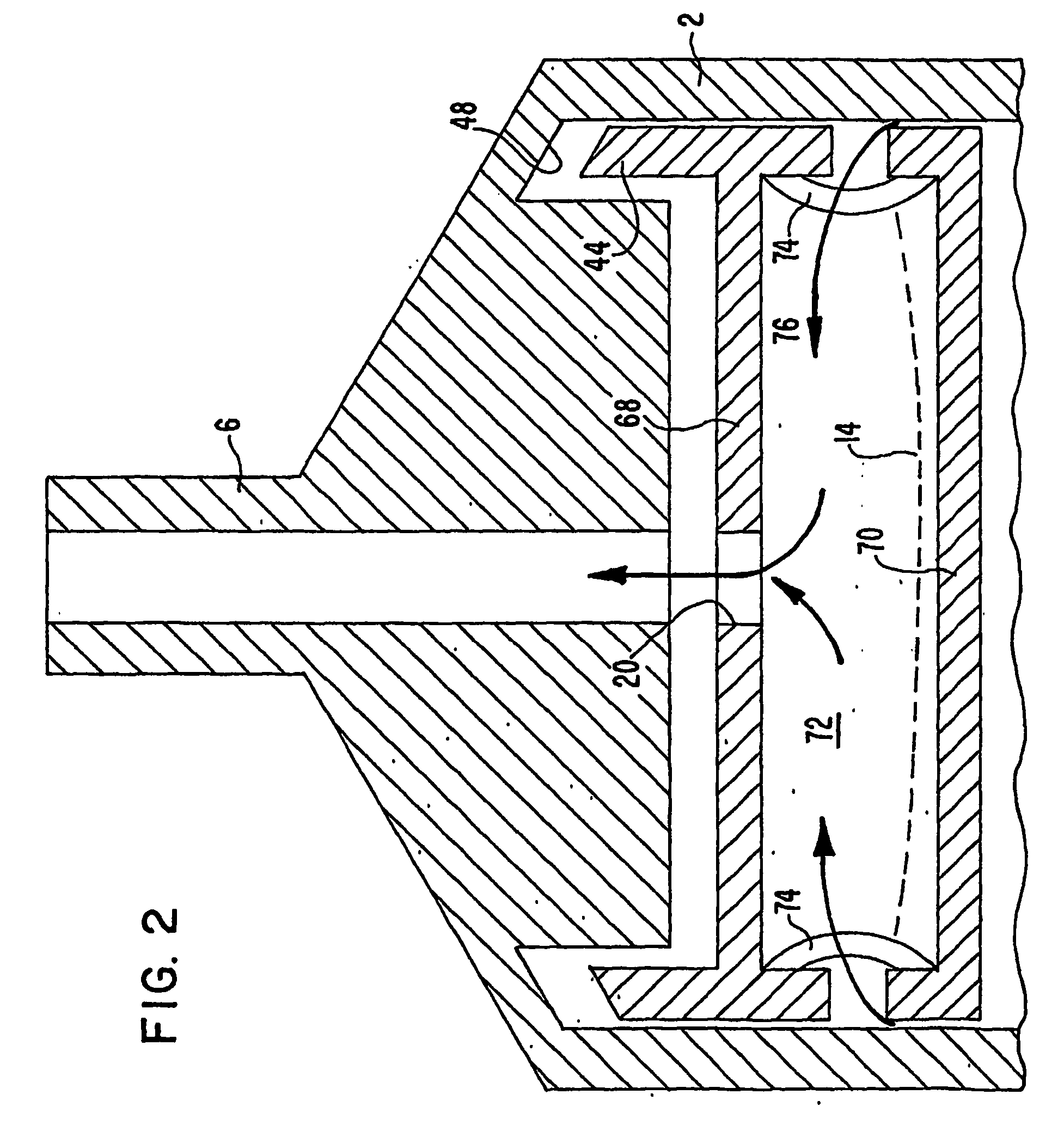
[0019] The invention also relates to perfecting mechanical features, such as a
handle for a
plunger that accommodates placing the syringe in a
centrifuge, and a stand for holding the syringe after centrifugation for facilitating expression of the components. The
handle may be detachable or flexible whereby the distance by which it extends from the end of the
barrel when the syringe is full is greatly reduced.
[0021] It is a further object of this invention to provide a syringe for withdrawing fluids from a container or from the patient, for being placed directly into a centrifuge, and for expressing the separated components in serial fashion with minimal mixing.

