
Simultaneous multi-alloy casting

a multi-alloy, simultaneous casting technology, applied in the direction of soldering apparatus, manufacturing tools, semiconductor/solid-state device details, etc., can solve the problems of increasing the cost of the final cladding product, the thickness of the cladding produced via roll bonding is generally limited to a maximum of about 35% of the total sheet thickness, and the roll bonding can be extremely difficul

Inactive Publication Date: 2009-11-03
ARCONIC INC
View PDF48 Cites 6 Cited by
  • Summary
  • Abstract
  • Description
  • Claims
  • Application Information

AI Technical Summary

Benefits of technology

This approach enables the production of multi-layered metal ingots with improved mechanical properties and reduced scrap losses by minimizing intermixing and allowing for a wider range of alloy combinations, while eliminating the need for roll bonding processes, thus enhancing productivity and product quality.

Problems solved by technology

Each of those processes adds to the cost of the final clad product.
In addition, the thickness of cladding produced via roll bonding is generally limited to a maximum of only about 35% of the total sheet thickness.
Roll bonding can also be extremely difficult if the mechanical properties of the alloys being roll bonded are too dissimilar at the rolling temperatures.
For example, when one alloy deforms very easily while the other alloy does not, the alloys do not seal properly or the target cladding ratio is off.
While this method provides some adhesion between the two components of the cast product, the mixing of the components which occurs during the casting can be detrimental to the finished product.
A drawback to this method is that the outer layer must solidify completely before the inner alloy can be cast within the outer layer.
The thickness of the outer layer also is limited because the heat of the inner component must exit through the outer layer to the exterior surfaces of the cast product.
Hence, the configuration of the final multi-component product also is limited.

Method used


Image

  • Simultaneous multi-alloy casting
  • Simultaneous multi-alloy casting
  • Simultaneous multi-alloy casting

Examples


examples 1-3

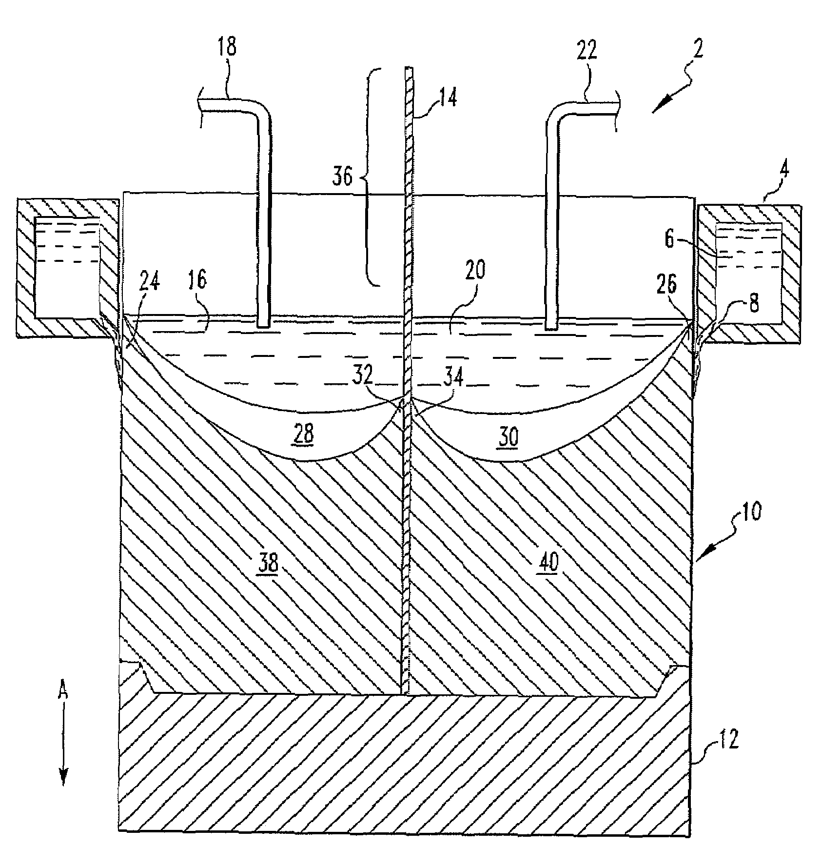
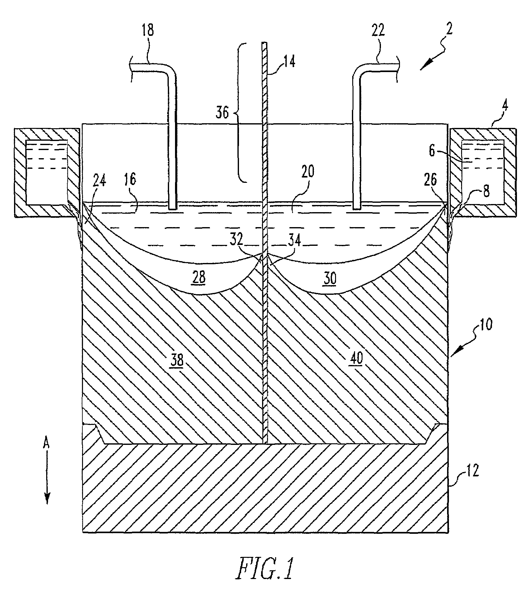
[0053]In each of Examples 1-3, a sheet of AA 1350 (20 inches wide, 0.375 inch thick, and 24 inches long) was positioned in the center of 12 inch×22 inch mold spanning the width with a gap of about 1 inch between the edge of the sheet and the mold walls. In each Example, a melt A of the alloy listed in Table 1 was poured into the mold on one side of the sheet and a melt B of the alloy B listed in Table 1 was poured into the mold on the other side of the sheet. In Example 3, flux was applied to the side of the sheet which contacted melt A. The metals were cast on opposing sides of the sheet while the bottom block with sheet seated thereon was lowered at a rate of 2.75 inches per minute. A 12 inch×22 inch×about 42 inch ingot having sheet of AA 1350 bonded between a layer of alloy A and a layer of alloy B was produced.

[0054]

TABLE 1Melt AMelt BExam-AATemp.Divider SheetAATemp.pleAlloy(° C.)AA alloyalloy(° C.)13003671*1350 7051**66723003664 + / − 313503005679 + / − 333003663 + / − 51350 with flu...


PUM

PropertyMeasurementUnit
solidus temperatureaaaaaaaaaa
temperatureaaaaaaaaaa
sizeaaaaaaaaaa

Abstract

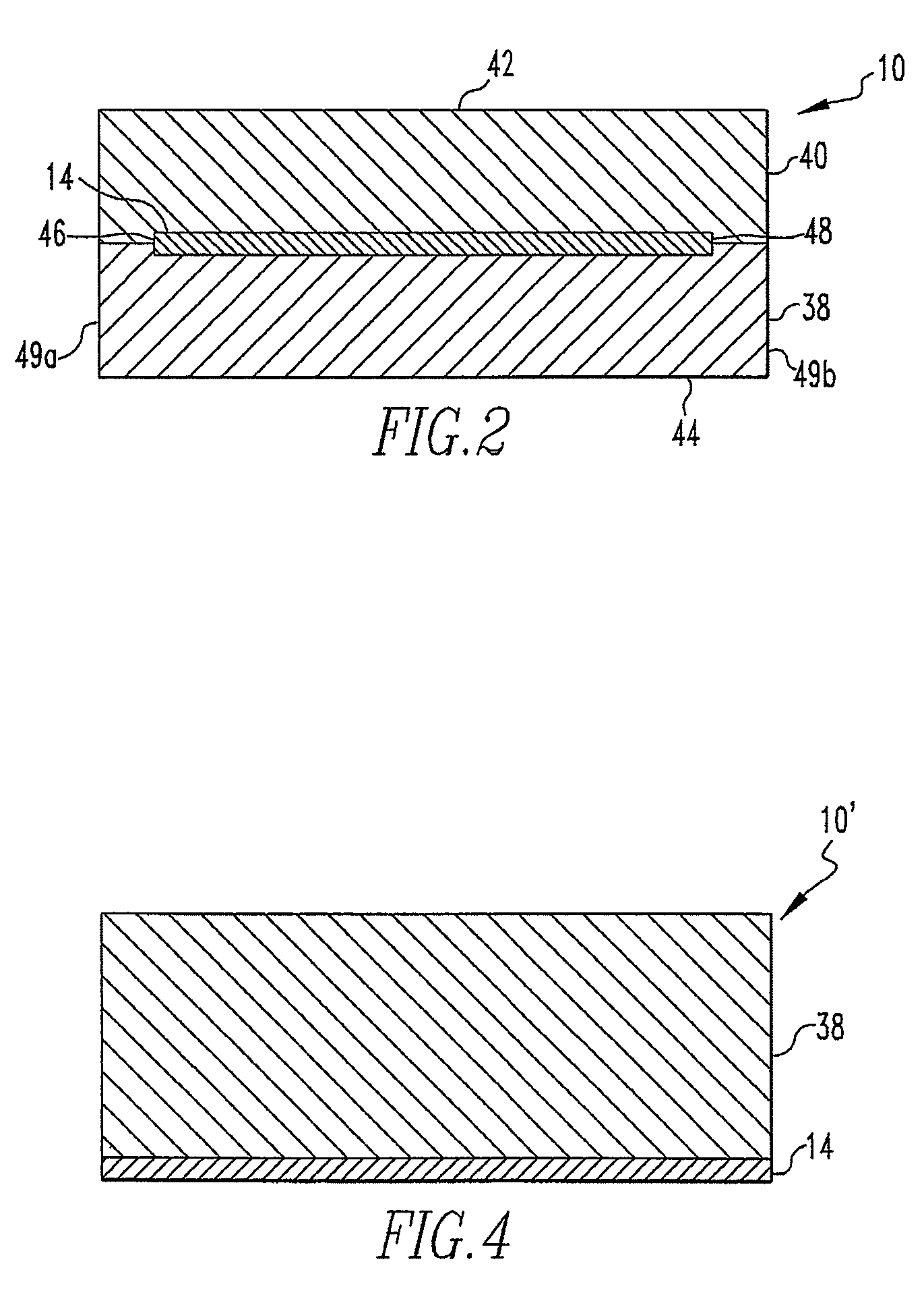
A method of casting a multi-layered metal ingot including the steps of delivering a metallic divider member into a direct chill mold, pouring a first molten metal into the mold on one side of the divider member, and pouring a second molten metal into the mold on the other side of the divider member, and allowing the first molten metal and the second molten metal solidify to form a metal ingot which includes the divider metal layer disposed there between.

Description

CROSS REFERENCE TO RELATED APPLICATION[0001]This patent application is a continuation of U.S. patent application Ser. No. 10 / 744,971, filed Dec. 22, 2003, now U.S. Pat. No. 7,407,713 which is a divisional of U.S. patent application Ser. No. 10 / 004,041, filed Oct. 23, 2001, now U.S. Pat. No. 6,705,384 entitled “Simultaneous Multi-Alloy Casting, each of which is incorporated herein by reference.BACKGROUND OF THE INVENTION[0002]1. Field of the Invention[0003]The present invention relates to the simultaneous casting of multiple alloys, in particular, direct chill casting of multiple aluminum alloys using a metallic member between the alloys to form a multi-component cast product and / or the use of a metallic member as an external layer on a cast ingot.[0004]2. Prior Art[0005]In the production of aluminum alloy ingots by a conventional direct chill (DC) casting process, molten aluminum is poured into an opened end mold. The lower end of the mold is initially closed by a platform referred ...

Claims


Application Information

Patent Timeline
Patent Type & Authority Patents(United States)
IPC IPC(8): B32B15/20B22D19/04B22D19/16B23K35/22B32B15/01B21B1/38B22D11/00B22D11/049
CPCB22D11/007B22D11/008B22D19/16B32B15/016B22D7/02C22C21/10C22C21/00B22D21/04Y10T428/12736Y10T428/12639Y10T428/12493Y10T428/12764Y10T428/12229Y10T428/12486B22D11/00
Inventor KILMER, RAYMOND J.KIRBY, JAMES L.
Owner ARCONIC INC
Learn More