Assembly with weld joint formed in hybrid welding process

a technology of hybrid welding and weld joints, which is applied in the direction of welding apparatus, manufacturing tools, transportation and packaging, etc., can solve the problems of high static and dynamic load on the separate inner ring and the flanged hub of the wheel bearing unit, and achieve the effect of acceptable fracture toughness

Active Publication Date: 2017-11-07
AB SKF
View PDF12 Cites 0 Cited by
  • Summary
  • Abstract
  • Description
  • Claims
  • Application Information

AI Technical Summary

Benefits of technology

[0007]In other words, the weld joint is formed with only a minimal amount of mixing between the filler material and the base material of the first and second steel components. The present inventor has found that a weld joint thus formed has excellent strength and toughness. Furthermore, the heat affected zone (HAZ) associated with the weld joint does not lead to an unacceptable increase in hardness, which would compromise the fracture toughness of the bearing steel.
[0010]The Nickel filler material provides good weld strength and toughness, and also creates a good interface between the molten weld pool and the base material(s).
[0014]The provision of a groove reduces the amount of steel that needs to be melted. If we assume that a weld depth of 7 mm is required and a groove with a depth of 4 mm (and a maximum width of 4.5 mm) is provided at the contact interface, the depth of the keyhole created by the energy beam only needs to be 3 mm. As a result, the amount of energy supplied from the energy beam is less likely to cause over-hardening in the HAZ. Furthermore, the power of the energy beam is selected depending on the depth of steel that needs to be melted, and is set as low as possible. Typically, the energy beam has a power of between 2000 and 7000 W.
[0021]The method of the invention allows a component made of through hardened bearing steel to be welded to a second steel component in a straightforward process, which results in a strong weld joint and a minimal heat affected zone with an acceptable fracture toughness.

Problems solved by technology

In use, the separate inner ring and the flanged hub of the wheel bearing unit experience high static and dynamic loads.

Method used


Image

  • Assembly with weld joint formed in hybrid welding process
  • Assembly with weld joint formed in hybrid welding process
  • Assembly with weld joint formed in hybrid welding process

Examples


Embodiment Construction

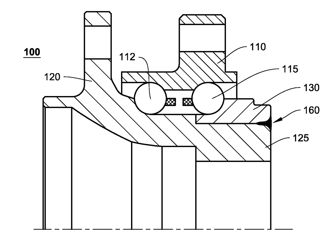
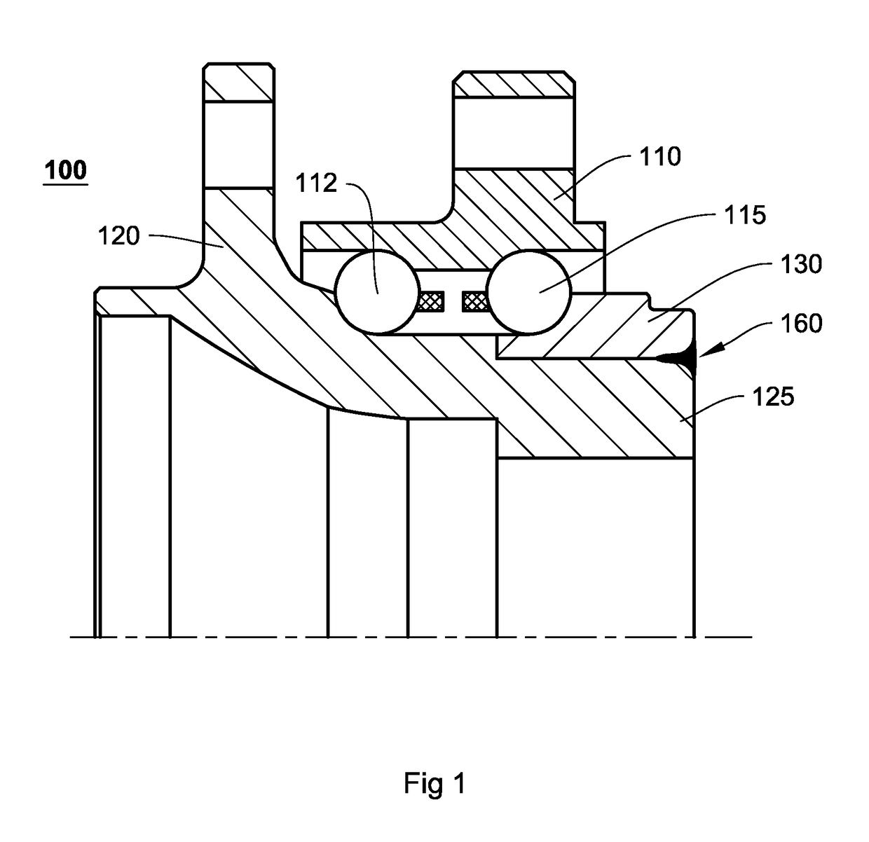
[0027]An example of part of an assembly comprising a weld joint formed in accordance with the invention is shown in cross-section in FIG. 1. The assembly is a wheel bearing unit 100 having an outer ring 110 with first and second outer raceways for accommodating a first row 112 and a second row 115 of rolling elements. The bearing unit further comprises a flanged inner ring 120 which has a first inner raceway for the first row of rolling elements 112. The second inner raceway for the second row of rolling elements 115 is provided on a separate inner ring 130. The separate inner ring is necessary in order to allow the second row of rolling elements 115 to be inserted into the hub unit after the outer ring 110 has been mounted over the first row 112. The separate inner ring 130 is mounted on a nose part 125 of the flanged inner ring 120. The separate inner ring is made of through-hardened bearing steel and the flanged inner ring (and nose part) is made of a hardenable steel, whereby th...


PUM

PropertyMeasurementUnit
depthaaaaaaaaaa
depthaaaaaaaaaa
depthaaaaaaaaaa

Abstract

An assembly includes a first steel component that is joined to a second steel component by a weld joint formed in a hybrid welding process. At least one of the first and second steel components is a through-hardened bearing steel. In the hybrid welding process, base material of the first and second steel components is melted, and a molten filler material including at least 90% nickel is added. The weld joint is formed after solidification of the molten base material and of the molten filler material. The weld joint has a central solidified portion and a peripheral solidified portion, and the central solidified portion includes at least 80% filler material and the peripheral solidified portion includes no more than 20% filler material.

Description

CROSS REFERENCE TO RELATED APPLICATION[0001]This is a National Stage application claiming the benefit of International Application Number PCT / EP2013 / 051468 filed on 25 Jan. 2013 (25 Jan. 2013), which claims the benefit of International Application Number PCT / EP2012 / 051542 filed on 31 Jan. 2012 (31 Jan. 2012), both of which are incorporated herein by reference in their entireties.FIELD OF THE INVENTION[0002]The present invention relates to an assembly comprising a first steel component joined to a second steel component by means of a weld joint formed in a hybrid welding process, whereby at least one of the first and second steel components comprises hardened bearing steel. The invention further relates to a method of forming the weld joint.BACKGROUND TO THE INVENTION[0003]Hybrid welding is a process in which the techniques of energy beam welding and gas metal arc welding (GMAW) are combined. As a result, the high speed and large penetration depth associated with e.g. laser welding c...

Claims


Application Information

Patent Timeline
Patent Type & Authority Patents(United States)
IPC IPC(8): B23K26/00B23K35/00F16C33/60F16C43/04B23K35/30B23K26/14B23K35/02B23K26/32F16C19/18B23K103/00
CPCB23K26/1429B23K26/32B23K35/004B23K35/0261B23K35/0288B23K35/3033F16C43/04F16C33/60Y10T428/12937B23K2203/50F16C19/186F16C2226/36F16C2326/02B23K26/348B23K2103/50
Inventor VAN DE SANDEN, JOHN F.
Owner AB SKF
Why Eureka
Try Eureka