Polymeric materials for site specific delivery to the body

a polymer material and site specific technology, applied in the direction of inorganic non-active ingredients, drugs, prostheses, etc., can solve the problems of high delivery pressure, thick walls of robust catheters, and high delivery pressur

Inactive Publication Date: 2004-08-12
MEDICAL GENESIS
View PDF13 Cites 8 Cited by
  • Summary
  • Abstract
  • Description
  • Claims
  • Application Information

AI Technical Summary

Problems solved by technology

The desirability of this high viscosity is offset by the problem of delivering these materials.
The transport of highly viscous materials through these catheters results in high shear stresses which, in turn, results in very high delivery pressures and requires very robust catheters.
In practice, however, robust catheters have thick walls and, accordingly, are not very flexible.
The lack of flexibility in the catheter makes the navigation through the vasculature upstream of the aneurysm difficult.
Even at this compromise viscosity, the treatment of aneurysms can be difficult.
Still further, the use of a liquid in the composition poses issues such as compatibility of the delivery devices with the li

Method used


Image

  • Polymeric materials for site specific delivery to the body
  • Polymeric materials for site specific delivery to the body

Examples


example 1

[0120] The purpose of this example is to demonstrate the preparation of a composition of this invention that is suitable, in one embodiment, for embolizing an aneurysm.

[0121] In a beaker, 15 g of EVOH (48 percent ethylene-average molecular weight of approximately 100,000) was added to 150 g of DMSO. The composition was covered and heated to 70.degree. C. for 1.5 hours while stirring at 500 RPM. The heating was continued at the indicated temperature until all of the EVOH was dissolved.

[0122] In a blender on low (18,000 RPM), containing the EVOH and DMSO, 88.04 g of tantalum powder was added over a period of one minute. Fumed silica (16.5 g of EH5) was then added into the vortex over approximately 2.5 minutes. After the addition of the last of the silica, the blender was ran for an additional 15 seconds. The blender was then run in the following cycles and the sides were scrapped in between the blending cycles; 1-minute, 1-minute, 1-minute, 2-minutes, 3-minutes, 3-minutes.
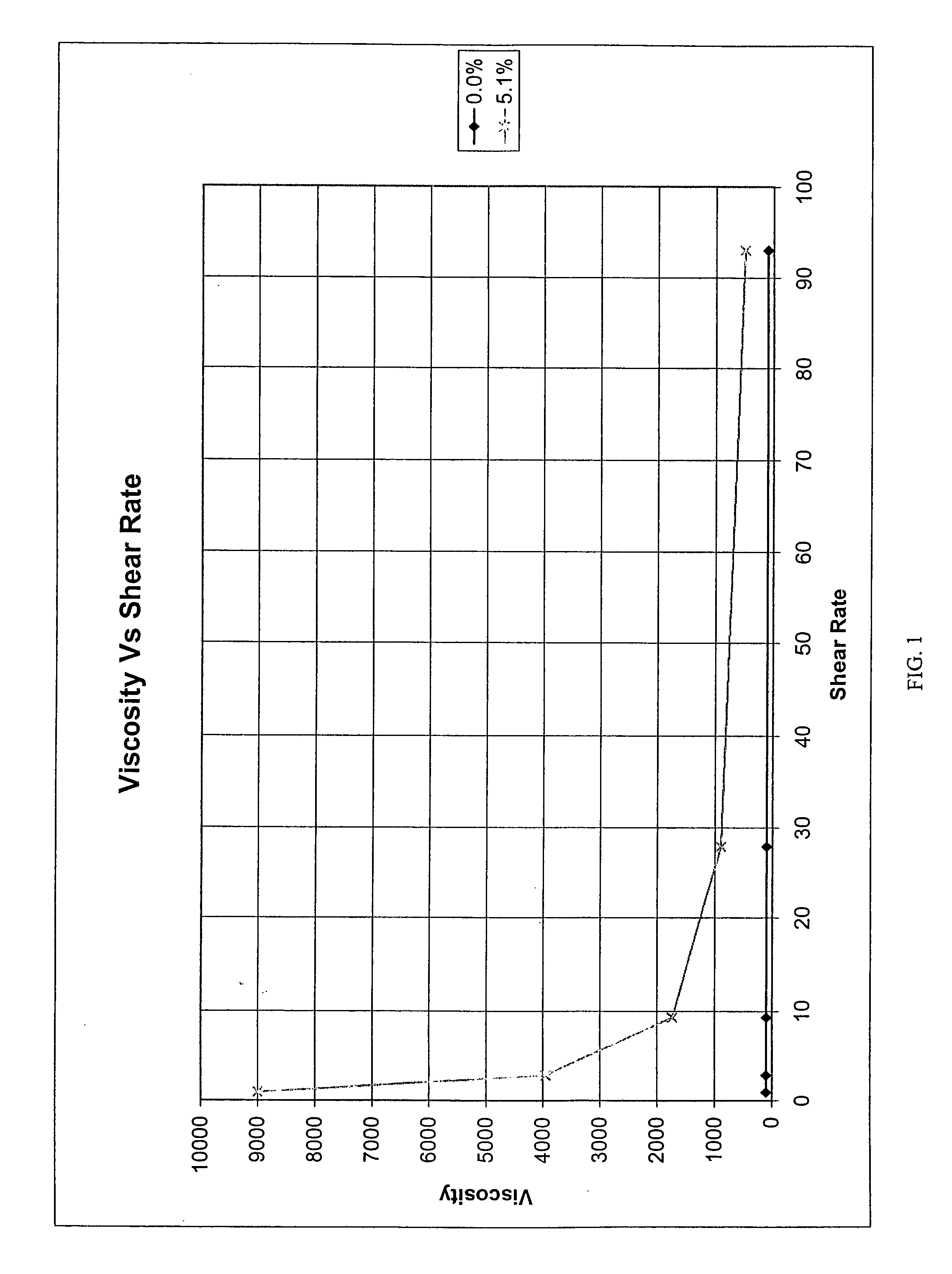
[0123] The v...

example 2

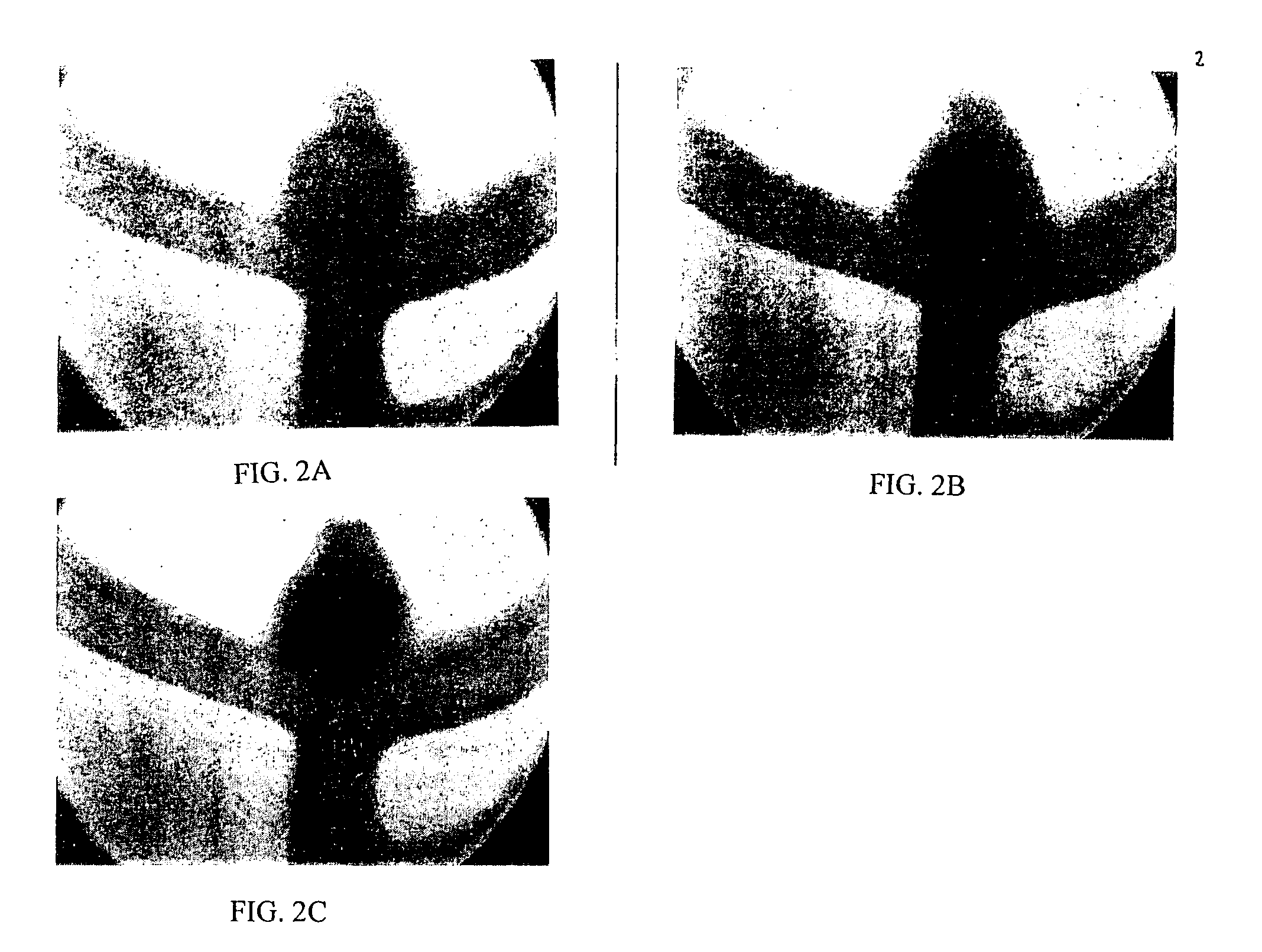
[0127] This example illustrates an in vitro application of a Theologically modified embolic composition. This composition was prepared in the manner of Example 1 above and was delivered via a catheter into a Y junction modified to have an artificial aneurysm at the juncture. While a flow of saline was maintained through the Y junction, the distal tip of a catheter was introduced into the artificial aneurysm and the composition was deposited over a time sufficient to fill the aneurysm. As illustrated in FIGS. 2A, 2B and 2C, a solid mass formed in the artificial aneurysm which effectively blocked the aneurysm from the systemic flow.

example 3

[0128] The purpose of this example is to illustrate how an in vivo application of the composition in the treatment of an aneurysm could be accomplished.

[0129] A 10-15 kg mongrel dog is anesthetized. Under sterile conditions and with the aid of an operating microscope, an experimental aneurysm is surgically created in the carotid artery using a jugular vein pouch, employing art recognized protocols. After about one week, the aneurysm is embolized with rheologically-modified composition.

[0130] Specifically, the femoral arteries are accessed by cut down and introducers and 7 Fr guiding catheters are placed.

[0131] For deposition of the rheologically-modified composition, a microcatheter (e.g., Micro Therapeutics, Inc. Rebar 14, with guide wire) is placed through the guiding catheter and is positioned under fluoroscopic guidance so that the catheter tip is in the aneurysmal sac. A microballoon catheter (4-5 mm balloon) is placed in the carotid artery proximal to the aneurysm. Position is...


PUM


Abstract

Disclosed are compositions for site specific delivery in the body including diseased vasculature (e.g., aneurysmal sacs, arteriovenous malformations, etc.), body lumens such as the vas deferens and fallopian tubes, cavities created in vivo for the purpose of tissue bulking, and the like. Also disclosed are methods employing such compositions as well as kits comprising such compositions.

Description

[0001] This application claims the benefit under 35 U.S.C. .sctn. 119(e) of U.S. Provisional Application 60 / 418,251, filed Oct. 15, 2002, which is hereby incorporated by reference in its entirety.FIELD OF THE INVENTION[0002] This invention relates to compositions for site specific delivery in the body including diseased vasculature (e.g., aneurysmal sacs, arteriovenous malformations, etc.), body lumens such as the vas deferens and fallopian tubes, cavities created in vivo for the purpose of tissue bulking and the like. This invention also relates to methods employing such compositions as well as kits comprising such compositions.[0003] The compositions of this invention comprise a non-reactive biocompatible substance and a sufficient amount of a rheological modifier to permit the composition to exhibit thixotropic behavior. This thixotropic behavior permits the compositions to exhibit high viscosities under static conditions while maintaining excellent flow properties under stress.R...

Claims


Application Information

Patent Timeline
IPC IPC(8): A61K9/00A61K47/02A61K47/32A61K49/00A61K49/04A61K51/06A61L24/00A61L24/04A61L27/50A61L31/18A61P43/00
CPCA61K9/0019A61K9/0024A61K47/02A61K47/32A61K49/0002A61K49/0409A61L31/18A61L24/001A61L24/0073A61L24/0089A61L24/043A61L27/50A61K51/06A61P43/00
Inventor PORTER, CHRISTOPHER H.ZIEBOL, ROBERT
Owner MEDICAL GENESIS
Why Eureka
Try Eureka