
Convertible roof bow control mechanism

Inactive Publication Date: 2006-07-13
SPECIALTY VEHICLE ACQUISITION
View PDF28 Cites 17 Cited by
  • Summary
  • Abstract
  • Description
  • Claims
  • Application Information

AI Technical Summary

Benefits of technology

[0004] The convertible vehicle top stack mechanism of the present invention is advantageous over traditional constructions in that the present invention reduces the activation forces required to move a rearmost roof bow relative to a side rail while also reducing acceleration spikes during movement of the rearmost roof bow. The present invention is further advantageous by providing movement of the convertible roof that limits the intrusion of the backlite into the passenger space during the retraction and raising operation thereby reducing the operating envelope of the convertible roof. Accordingly, the present invention reduces part failure during usage, is easier to control, and requires a smaller operating space. Additional advantages and features of the present invention will become apparent from the following description and appended claims, taken in conjunction with the accompanying drawings.

Problems solved by technology

It is noteworthy, however, that many traditional number five bow actuation systems have required undesirably high forces to operate which necessitates difficult to package, large and expensive hydraulic cylinders while increasing the chance of premature part failure.
Furthermore, many of these traditional systems disadvantageously create undesirably fast acceleration of the number five bow during movement which can lead to premature part failure.
Moreover, many of these traditional systems also disadvantageously push the backlite or rear window into the rear passenger area of the vehicle thereby limiting the usable passenger space during the raising and retracting of the convertible roof.

Method used


Image

  • Convertible roof bow control mechanism
  • Convertible roof bow control mechanism
  • Convertible roof bow control mechanism

Examples


Embodiment Construction

[0016] The following description of the preferred embodiment is merely exemplary in nature and is in no way intended to limit the invention, its application, or uses.

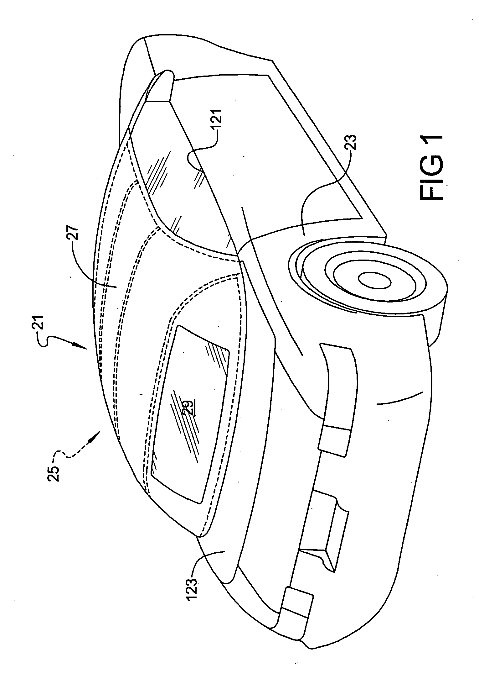
[0017] The preferred embodiment of a convertible roof 21 attached to an automotive vehicle body 23 of the present invention is shown in FIG. 1. Only one side of convertible roof 21 will be discussed herein since the other side is essentially a mirrored image of the one discussed and illustrated. Convertible roof 21 includes a top stack mechanism 25 which is covered by a pliable or flexible fabric cover 27 which has a solid glass back window or backlite 29, or alternately a flexible PVC window, attached thereto.

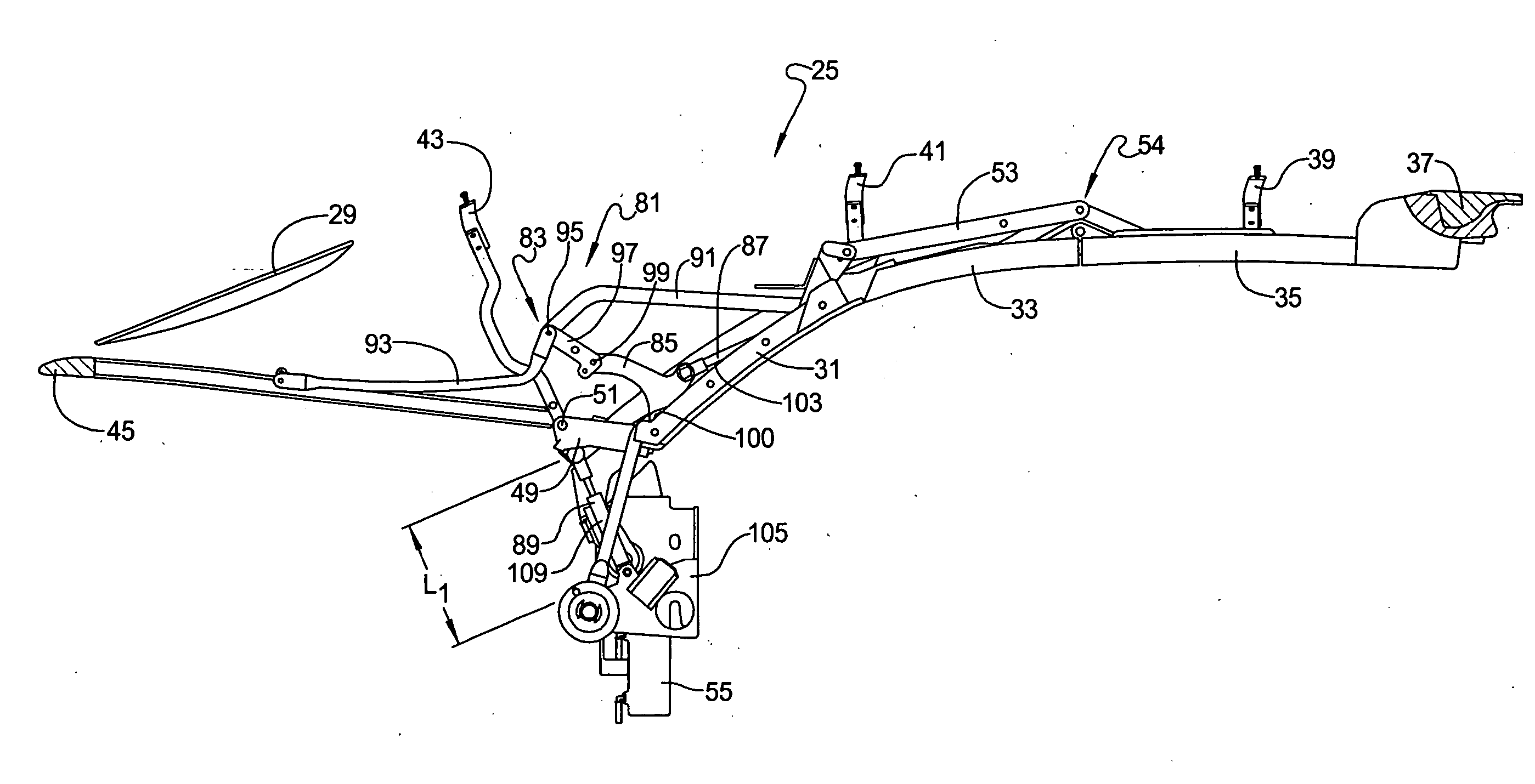
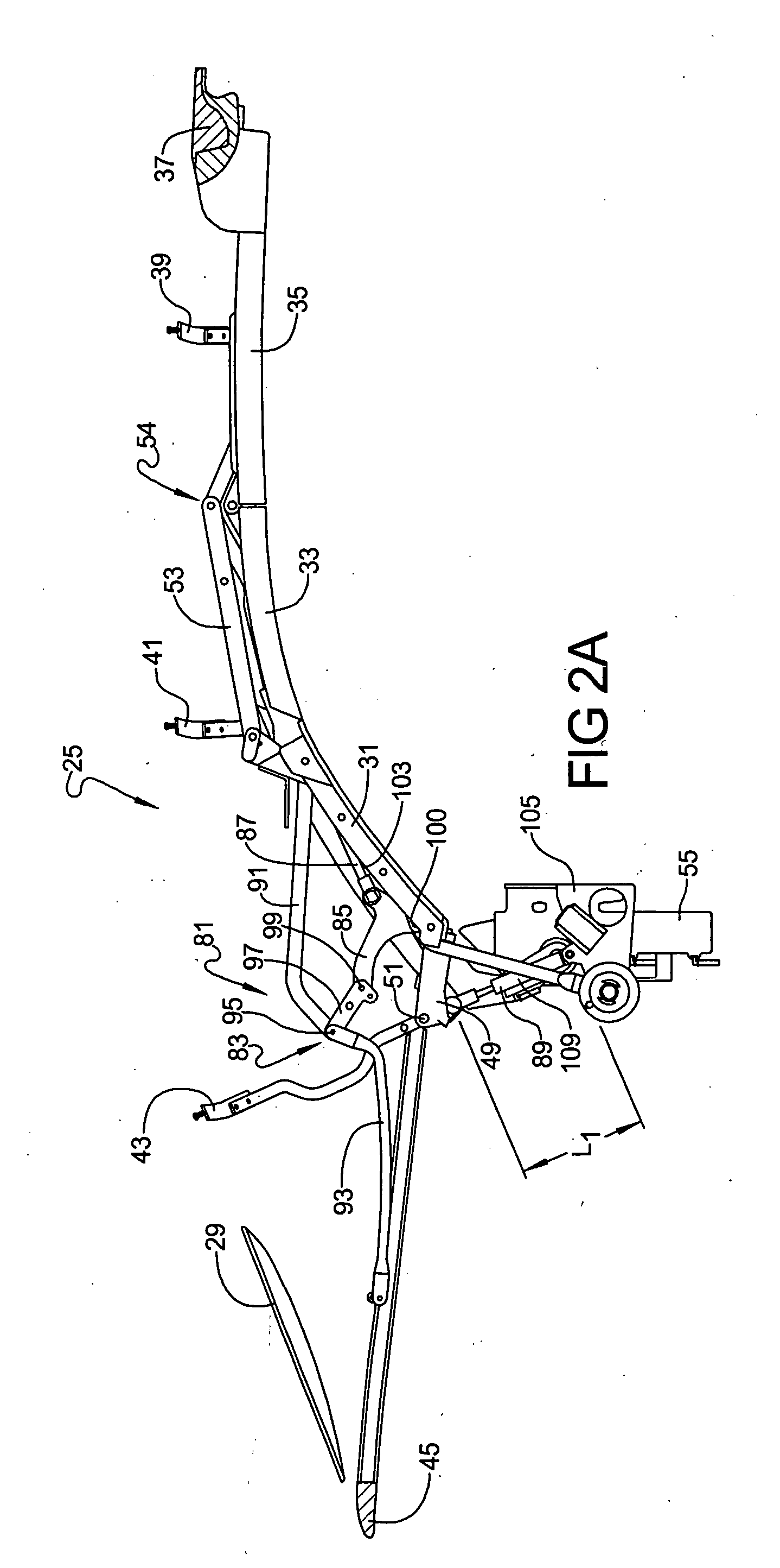
[0018] Referring to FIGS. 2A-5B, top stack mechanism 25 includes a rear side rail 31, a center side rail 33 and a front side rail 35. A forwardmost or number one roof bow 37 is attached to front side rail 35, a number two roof bow 39 is pivotally coupled to center side rail 33, a number three roof bow 41 is pivo...


PUM


Abstract

A vehicle convertible roof including a rearmost roof member, a side roof rail, an actuator and a link having a length that varies between a first length and a second as the rearmost roof member moves between a nominal and raised position. The adjustable length link is fixed at the second length during retraction and extension of the side roof rail of the vehicle convertible roof.

Description

BACKGROUND AND SUMMARY OF THE INVENTION [0001] The present invention relates generally to automotive vehicle convertible roofs and more particularly to a convertible vehicle top stack mechanism having an active rearmost roof bow. [0002] Some traditional convertible roofs for automotive vehicles employ an active number five bow which can be selectively rotated from a nominal and generally horizontal position to a raised and generally vertical position in order to allow clearance for a moveable, rigid tonneau cover. Such a tonneau cover needs to be opened to allow convertible roof access for retraction into a storage compartment or boot well, and the tonneau cover is closed so the number five roof bow can sit on top of it when the convertible roof is fully raised. One such example is disclosed in U.S. Pat. No. 6,039,382 entitled “Folding Top for a Motor Vehicle” which issued to Mather et al., on Mar. 21, 2000, and is incorporated by reference herein. Hydraulically driven buggy links h...

Claims


Application Information

Patent Timeline
IPC IPC(8): B60J7/00
CPCB60J7/1265
Inventor SCHARTNER, TODDDULEY, SCOTT
Owner SPECIALTY VEHICLE ACQUISITION
Learn More