3D spectral imaging system and method based on scattering medium

A spectral imaging and medium technology, applied in the field of 3D spectral imaging system based on scattering medium, can solve problems such as time resolution reduction, and achieve good spectral resolution, good imaging effect, and low cost.

Active Publication Date: 2019-09-24
XIDIAN UNIV
View PDF8 Cites 20 Cited by
  • Summary
  • Abstract
  • Description
  • Claims
  • Application Information

AI Technical Summary

Problems solved by technology

To achieve 3D spectral imaging on the basis of traditional spectral imaging technology, it is necessary to combine optical scanning 3D imaging technology and multi-frame 3D imaging technology. Although 3D imaging can be achieved, its temporal resolution is greatly reduced.

Method used


Image

  • 3D spectral imaging system and method based on scattering medium
  • 3D spectral imaging system and method based on scattering medium
  • 3D spectral imaging system and method based on scattering medium

Examples


Embodiment 1

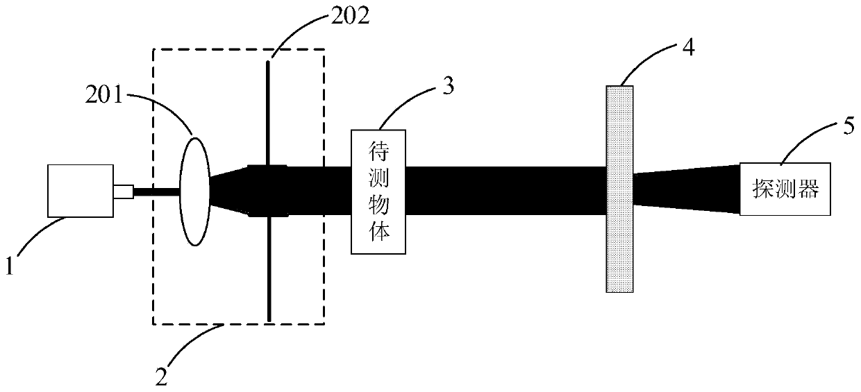
[0045] See figure 1 , figure 1 It is a schematic structural diagram of a 3D spectral imaging system based on a scattering medium provided by an embodiment of the present invention. As shown in the figure, the 3D spectral imaging system based on a scattering medium in this embodiment includes a light source module 1, A collimation correction module 2, an object to be measured 3, a scattering medium 4 and a detector 5, wherein the light source module 1 is used to generate a beam of arbitrary wavelength, and the collimation correction module 2 is used to perform collimation correction and filter out the light beam Impurity astigmatism, the light beam after collimation correction and filtering of impurity astigmatism is irradiated on the object 3 to be measured, the scattering medium 4 is used to scatter the light passing through the object 3 to form a speckle pattern, and the detector 5 is used to receive The speckle map.

[0046] Specifically, the light source module 1 is comp...

Embodiment 2

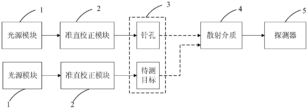
[0064] See Figure 4 , Figure 4 is a schematic diagram of a 3D spectral imaging method based on a scattering medium provided by an embodiment of the present invention. The overall composition of the 3D spectral imaging system based on the scattering medium is the same as that of Embodiment 1, and the 3D spectral imaging method includes:

[0065] S1: Collect and calibrate the calibrated speckle images of different wavelengths and different depth-of-field distances, and construct the system PSF database;

[0066] Specifically, before step S1, it also includes building the 3D spectral imaging system based on the scattering medium, turning on the light source module 1, and sequentially setting the collimation correction module 2, the object to be measured 3, the scattering medium 4 and the detector 5 along the direction of the optical path. , wherein the object to be measured 3 is a pinhole with a diameter of 100 μm.

[0067] Please refer to Figure 5 , Figure 5 It is a sch...


PUM

PropertyMeasurementUnit
thicknessaaaaaaaaaa

Abstract

The invention relates to a 3D spectral imaging system and method based on a scattering medium. The system comprises a light source module, a collimation correction module, a to-be-tested object, a scattering medium and a detector that are arranged in sequence along the optical path direction. The light source module is used for generating a light beam with the random wavelength. The collimation correction module is configured to perform collimation correction and impurity astigmatism filtering on the light beam. The beam after the collimation correction and impurity astigmatism filtering irradiates the to-be-tested object. The scattering medium is configured to scatter light passing through the to-be-tested object to form a speckle pattern. The detector is configured to receive the speckle pattern. According to the provided system and method, with the scattering medium for replacing the conventional single lens, a PSF database containing spectral and spatial depth information is established and a target is rebuilt by combining a deconvolution method, so that the spectral information and three-dimensional structural information of the to-be-tested object are simultaneously displayed. Therefore, the 3D spectral imaging system and method have the good spectral resolution and good imaging result.

Description

technical field [0001] The invention belongs to the technical field of computational imaging, and in particular relates to a 3D spectral imaging system and method based on a scattering medium. Background technique [0002] According to the principle, traditional spectral imaging can be divided into four types: filter type, dispersion type, interference type and computational spectral imaging. With the development of science and technology, 3D spectral imaging has received more and more attention and applications in the fields of astronomical observation, remote sensing measurement, chemical and material analysis, biomedical imaging, and non-destructive testing of light source characteristics. To achieve 3D spectral imaging on the basis of traditional spectral imaging technology, it is necessary to combine optical scanning 3D imaging technology and multi-frame 3D imaging technology. Although 3D imaging can be achieved, its temporal resolution is greatly reduced. [0003] Wit...

Claims


Application Information

Patent Timeline
Patent Type & Authority Applications(China)
IPC IPC(8): G01N21/25
CPCG01N21/25
Inventor 邵晓鹏朱磊张乐刘杰涛吴雨祥刘飞
Owner XIDIAN UNIV
Why Eureka
Try Eureka