Method and apparatus for a frequency diverse array

Active Publication Date: 2006-07-13
THE UNITED STATES OF AMERICA AS REPRESETNED BY THE SEC OF THE AIR FORCE
View PDF13 Cites 53 Cited by
  • Summary
  • Abstract
  • Description
  • Claims
  • Application Information

AI Technical Summary

Benefits of technology

[0011] The present invention provides a range dependent beamformer. Different signals are applied to each radiating element. Input signals are controlled such that the combined signal focuses in different directions depending on range. In the fundamental embodiment of the present invention, the range dependent beamformer simultaneously applies a small but fixed frequency shift relative from one radiating element to the next radiating element. This adds two new terms to the formulation of the phase path difference between any two adjacent elements. Both new terms are dependent on the applied frequency shift, and one of the terms is also dependent upon range. The present invention therefore results in beam focusing and beam pointing that vary with range. Alternative embodiments of the present invention provide for the control of adaptive transmit signals resulting in multiple transmit beams without spoiling, and simultaneous use of radiated energy for multiple conflicting requirements.

Problems solved by technology

A limitation of the prior art is that, for any instant of time, beam steering is fixed in angle for all ranges.

Method used


Image

  • Method and apparatus for a frequency diverse array
  • Method and apparatus for a frequency diverse array
  • Method and apparatus for a frequency diverse array

Examples


Embodiment Construction

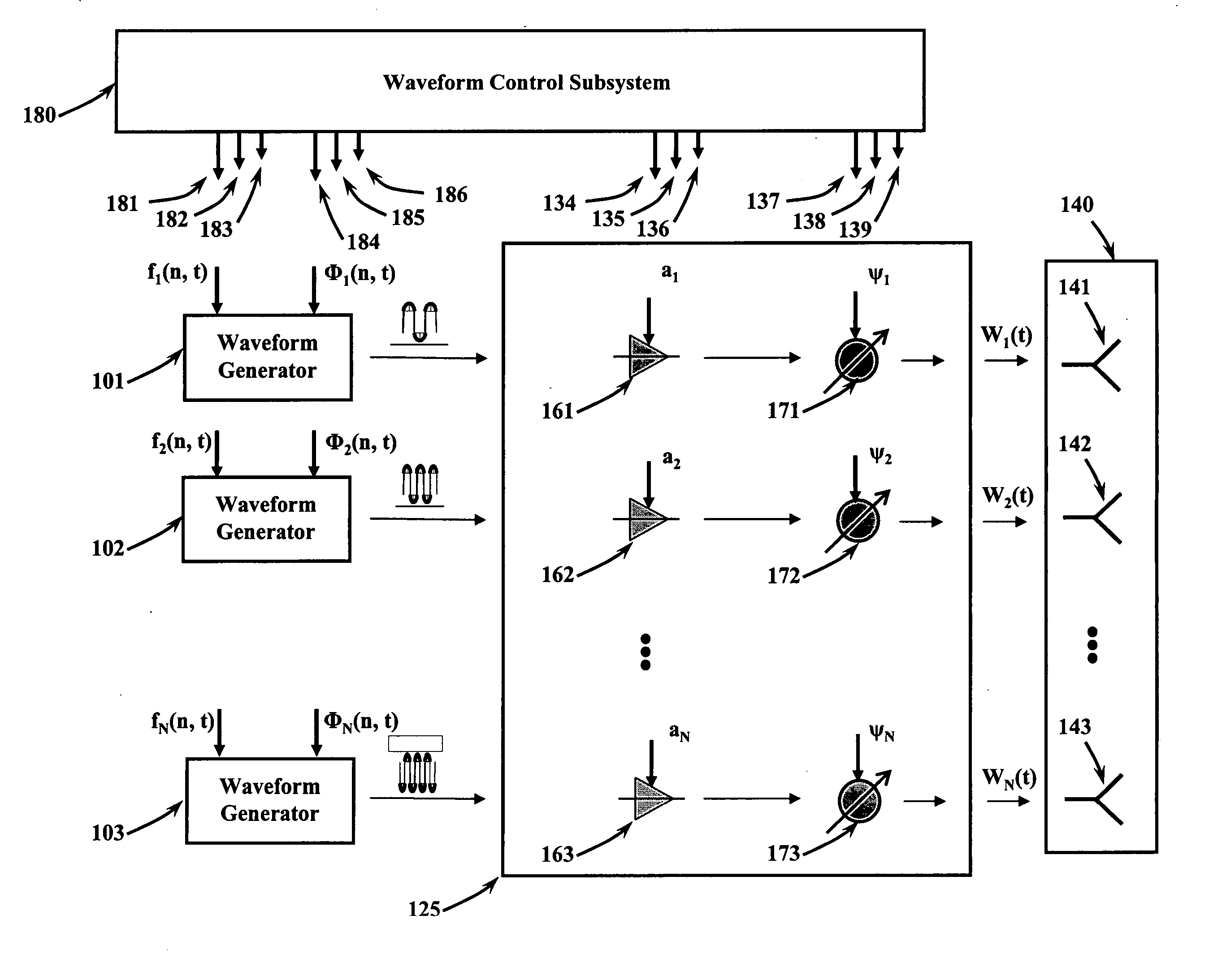
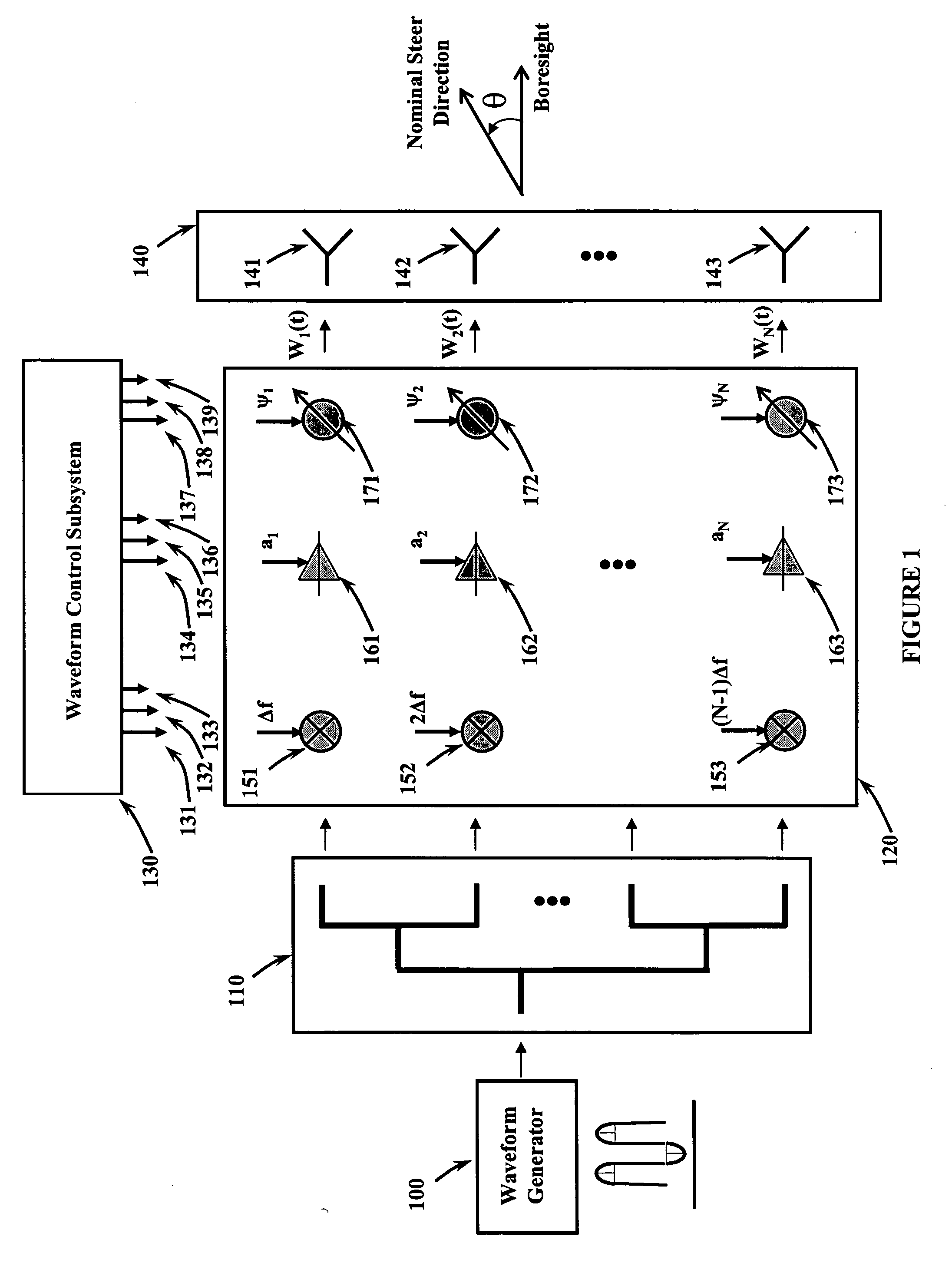
[0031] Referring to FIG. 1, the key components of a generic range dependent beamformer include a waveform generator 100, a power divider network 110, which is a conventional corporate feed network in the preferred embodiment, a transmitter / receiver module 120, a waveform control subsystem 130, and a radiating element array 140.

[0032] The waveform generator 100 synthesizes a signal to be transmitted. This signal is distributed to each of the first and second through the nth radiating / receiving elements 141, 142, 143 by means of a power divider network 110. The signal output of each of the power divider network 110 outputs is input to a transmitter / receiver module 120. The transmitter / receiver module 120 consists of a set of first and second through an nth modulator 151, 152, 153 followed by a first and a second through an nth radio frequency amplifier 161, 162, 163 and a first and second through an nth phase shifter 171, 172, 173. The transmitter / receiver module 120 is controlled by...


PUM


Abstract

Method and apparatus for a frequency diverse array. Radio frequency signals are generated and applied to a power divider network. A progressive frequency shift is applied to all radio frequency signals across all spatial channels. Amplitude weighting signals are applied for sidelobe control. Phase control is included for channel compensation and to provide nominal beam steering. The progressive frequency offsets generate a new term which cause the antenna beam to focus in different directions as a function of range. Alternative embodiments generate different waveforms to be applied to each radiating element, permitting the transmission of multiple signals at the same time.

Description

PRIORITY CLAIM UNDER 35 U.S.C. §119(e) [0001] This patent application claims the priority benefit of the filing date of provisional application Ser. No. 60 / 643,431, having been filed in the United States Patent and Trademark Office on Jan. 12, 2005 and now incorporated by reference herein.STATEMENT OF GOVERNMENT INTEREST [0002] The invention described herein may be manufactured and used by or for the Government for governmental purposes without the payment of any royalty thereon.BACKGROUND OF THE INVENTION [0003] This invention relates generally to the field of electronically-scanned phased array antennas. More specifically, the present invention relates to electronic beamformers for such antennas. [0004] Phased array antennas have been developed to provide electronic beam steering of radiated or received electromagnetic signals. In traditional phased arrays, the signal applied to all radiating elements is identical. An amplifier is often placed near the radiating element to provide...

Claims


Application Information

Patent Timeline
Patent Type & Authority Applications(United States)
IPC IPC(8): G01S13/90
CPCG01S13/9035G01S2013/9041G01S2013/9052G01S13/904G01S13/9041G01S13/9052G01S13/9054
Inventor WICKS, MICHAEL C.ANTONIK, PAUL
Owner THE UNITED STATES OF AMERICA AS REPRESETNED BY THE SEC OF THE AIR FORCE
Why Eureka
Try Eureka