Zoom lens and imaging system incorporating it

Inactive Publication Date: 2006-07-13
OLYMPUS CORP
View PDF11 Cites 29 Cited by
  • Summary
  • Abstract
  • Description
  • Claims
  • Application Information

AI Technical Summary

Benefits of technology

[0018] In view of such situations of the prior art as described above, an object of the invention is to provide a zoom lens t

Problems solved by technology

The greatest bottleneck to slimming down the depth dimension of a camera is the thickness of an optical system, especially a zoom lens system, from the surface nearest to the object side to the imaging plane.
However, its pixel pitch must be smaller so as to maintain the same number of pixels, and poor sensitivity must be compensated for

Method used


Image

  • Zoom lens and imaging system incorporating it
  • Zoom lens and imaging system incorporating it
  • Zoom lens and imaging system incorporating it

Examples


examples 2-5

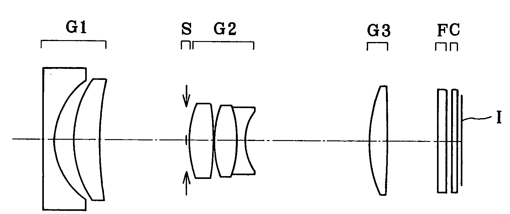
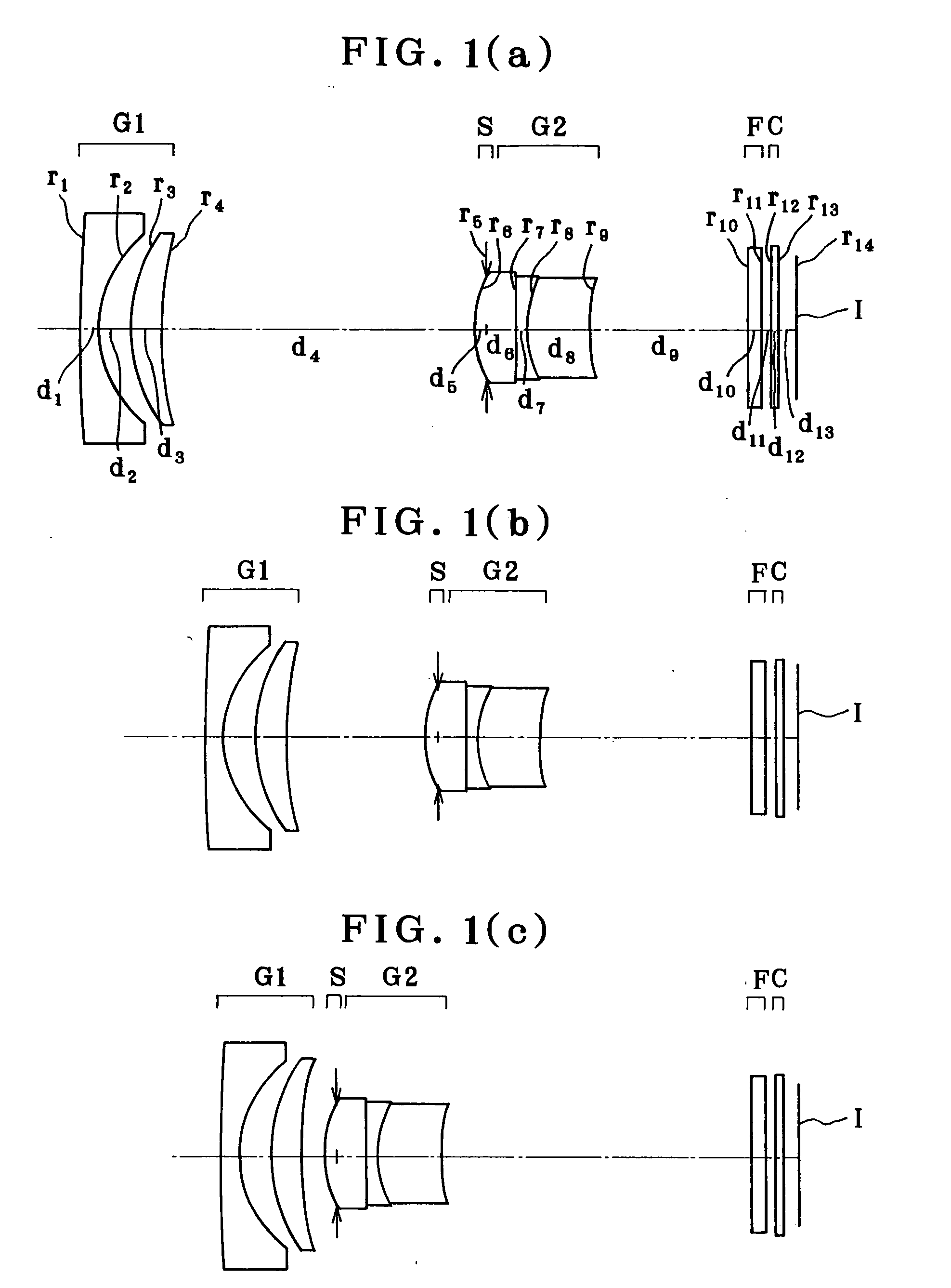
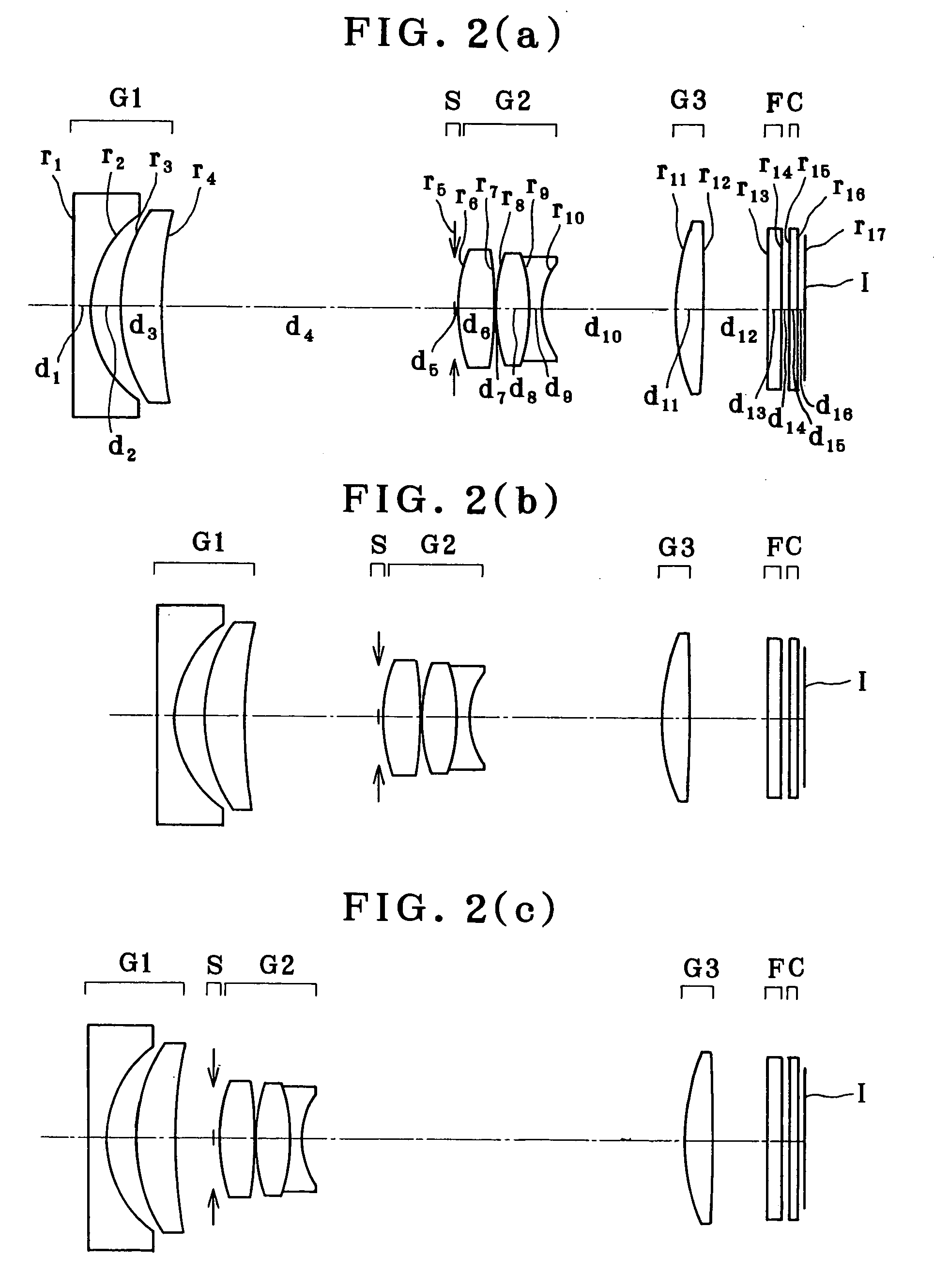
[0281] As depicted in FIG. 2, these examples are each directed to a zoom lens made up of, in order from its object side, a first lens unit G1 of negative refracting power, an aperture stop S, a second lens unit G2 of positive refracting power and a third lens unit G3 of positive refracting power. Upon zooming from the wide-angle end to the telephoto end, the first lens unit G1 moves in a convex locus toward the image plane side and is positioned nearer to the object side at the telephoto end than in the intermediate setting and somewhat nearer to the image side at the telephoto end than at the wide-angle end, the aperture stop S and the second lens unit G2 move together monotonously toward the object side, and the third lens unit G3 moves in a convex locus toward the object side and is positioned somewhat nearer to the image side at the telephoto end than at the wide-angle end.

[0282] In order from the object side, the first lens unit G1 is composed of a negative meniscus lens conve...

example 1

[0297]

r1 = 108.042d1 = 1.20nd1 = 1.76802νd1 = 49.24r2 = 6.708 (Aspheric)d2 = 2.10r3 = 10.793d3 = 2.02nd2 = 1.90366νd2 = 31.31r4 = 23.068d4 = (Variable)r5 = ∞ (Stop)d5 = −0.85r6 = 6.848 (Aspheric)d6 = 2.71nd3 = 1.77377νd3 = 47.18r7 = 108.781d7 = 0.80nd4 = 1.80518νd4 = 25.43r8 = 7.546d8 = 4.11nd5 = 1.58313νd5 = 59.46r9 = 29.503 (Aspheric)d9 = (Variable)r10 = ∞d10 = 0.95nd6 = 1.54771νd6 = 62.84r11 = ∞d11 = 0.55r12 = ∞d12 = 0.50nd7 = 1.51633νd7 = 64.14r13 = ∞d13 = 1.02r14 = ∞ (Image plane)Aspherical Coefficients2nd surfaceK = −0.294A4 = −7.55134 × 10⁻⁵A6 = −5.49709 × 10⁻⁷A8 = −4.99503 × 10⁻⁸A10 = 1.19213 × 10−126th surfaceK = −0.845A4 = 3.13655 × 10⁻⁴A6 = 6.27405 × 10⁻⁸A8 = 3.18418 × 10⁻⁷A10 = −5.48797 × 10−99th surfaceK = −0.299A4 = 1.52846 × 10⁻³A6 = −6.38153 × 10⁻⁶A8 = 8.63601 × 10⁻⁶A10 = −5.05358 × 10⁻⁷A12 = 2.28142 × 10⁻⁸Zooming Data (∞)WESTTEf (mm)8.20313.49923.275FNO3.173.895.212ω (°)60.537.121.8d421.119.712.30d99.7313.2319.70

example 2

[0298]

r1 = 486.879d1 = 1.20nd1 = 1.74330νd1 = 49.33r2 = 6.572 (Aspheric)d2 = 1.84r3 = 11.096d3 = 2.64nd2 = 1.90366νd2 = 31.31r4 = 29.983d4 = (Variable)r5 = ∞ (Stop)d5 = 0.20r6 = 9.565 (Aspheric)d6 = 2.40nd3 = 1.58313νd3 = 59.46r7 = −32.947 (Aspheric)d7 = 0.10r8 = 10.752d8 = 2.31nd4 = 1.77250νd4 = 49.60r9 = −10.752d9 = 0.70nd5 = 1.64769νd5 = 33.79r10 = 5.145d10 =(Variable)r11 = 15.888d11 = 1.74nd6 = 1.58313νd6 = 59.46r12 = −92.317 (Aspheric)d12 =(Variable)r13 = ∞d13 = 0.86nd7 = 1.54771νd7 = 62.84r14 = ∞d14 = 0.50r15 = ∞d15 = 0.50nd8 = 1.51633νd8 = 64.14r16 = ∞d16 = 0.43r17 = ∞ (Image plane)Aspherical Coefficients2nd surfaceK = −0.639A4 = −2.98759 × 10⁻⁵A6 = 3.27427 × 10⁻⁶A8 = −1.20087 × 10⁻⁷A10 = 1.35884 × 10−96th surfaceK = 0.000A4 = −2.50030 × 10⁻⁴A6 = −5.47642 × 10⁻⁶A8 = −2.75670 × 10⁻⁷A10 = 7.44525 × 10−107th surfaceK = 0.000A4 = 1.00025 × 10⁻⁵A6 = −4.46990 × 10⁻⁶A8 = −2.98489 × 10⁻⁷A10 = 5.19077 × 10−912th surfaceK = 0.000A4 = 9.29735 × 10⁻⁵A6 = −3.43799 × 10⁻⁶A8 = 5.61229 × 10−...


PUM


Abstract

The invention relates to a small-format yet high-performance two units or three units type zoom lens with a negative unit at the front, which has a zoom ratio of about 3, an angle of view of as wide as 60° at the wide-angle end and high image-formation capability, and is much less susceptible to chromatic blurring, with a compact lens barrel. The zoom lens comprises a first lens unit G1 of negative refracting power and a second lens unit G2 of positive power, wherein zooming is implemented by varying the space between the lens units. The first lens unit G1 is made up of one negative lens L11 and one positive lens L12, two in all, and satisfies specific conditions with respect to their refractive index and Abbe constant.

Description

[0001] This application claims benefit of Japanese Application Nos. 2005-3991 and 2005-3992 filed in Japan on Jan. 11, 2005, the contents of which are incorporated by this reference. BACKGROUND OF THE INVENTION [0002] The present invention relates generally to a zoom lens and an imaging system that incorporates it, and more particularly to a zoom lens well suitable for use with electronic imaging systems such as digital cameras and video cameras, wherein depth size upon received at a collapsible lens mount is reduced by tweaks applied to an optical system portion such as a zoom lens, and an imaging system. [0003] In recent years, digital cameras have attracted attention as next-generation cameras superceding silver-halide 35-mm film cameras. In addition, they are now available in some considerable categories covering every type from the business-application, multifunctional type to the portable low-end type. [0004] In view of the portable, low-end type category in particular, one sp...

Claims


Application Information

Patent Timeline
IPC IPC(8): G02B15/14
CPCG02B15/177G02B15/143507
Inventor SATORI, TOMOYUKI
Owner OLYMPUS CORP
Why Eureka
Try Eureka