Network interface device having integral slack storage compartment

a network interface and storage compartment technology, applied in the field of enclosures, can solve the problems of requiring the nid to have a relatively large footprint and occupy a significant amount of spa

Inactive Publication Date: 2006-07-13
CORNING CABLE SYST LLC
View PDF99 Cites 185 Cited by
  • Summary
  • Abstract
  • Description
  • Claims
  • Application Information

AI Technical Summary

Benefits of technology

[0011] The invention will be understood more easily and other objects, characteristics, details and advantages thereof will become more apparent in the course

Problems solved by technology

As a result, the NID is usually mounted in a location having restricted access, such as a utility closet inside the subscriber premises.
Typically, the passive or active components belonging to the service provid

Method used


Image

  • Network interface device having integral slack storage compartment
  • Network interface device having integral slack storage compartment
  • Network interface device having integral slack storage compartment

Examples


Embodiment Construction

[0027] The invention is described more fully hereinafter with reference made to the accompanying drawings, in which preferred embodiments of the invention are shown. The invention may, however, be embodied in many different forms, and therefore, should not be construed as being limited to the particular embodiments shown and described herein. Illustrative embodiments are set forth herein so that this description will be both thorough and complete, and will fully convey the intended scope of the claimed invention while enabling those skilled in the art to make and practice the invention without undue experimentation. Positional terms, such as left, right, top, bottom, front, rear, side, etc., and relational terms, such as larger, smaller, nearer, farther, etc., are utilized herein for purposes of explanation only, and as such, should not be construed as limiting the scope of the invention or the appended claims in any manner.

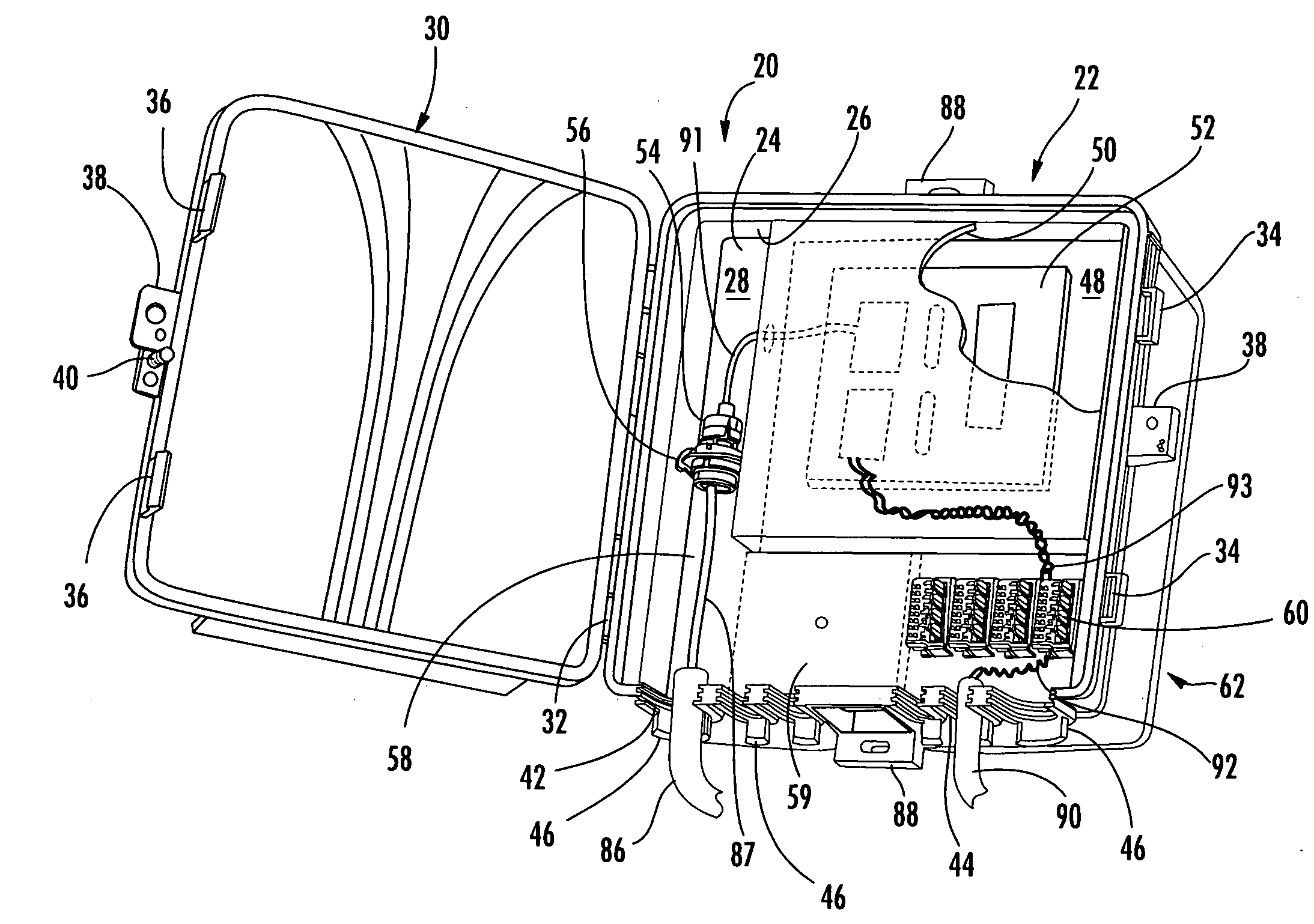
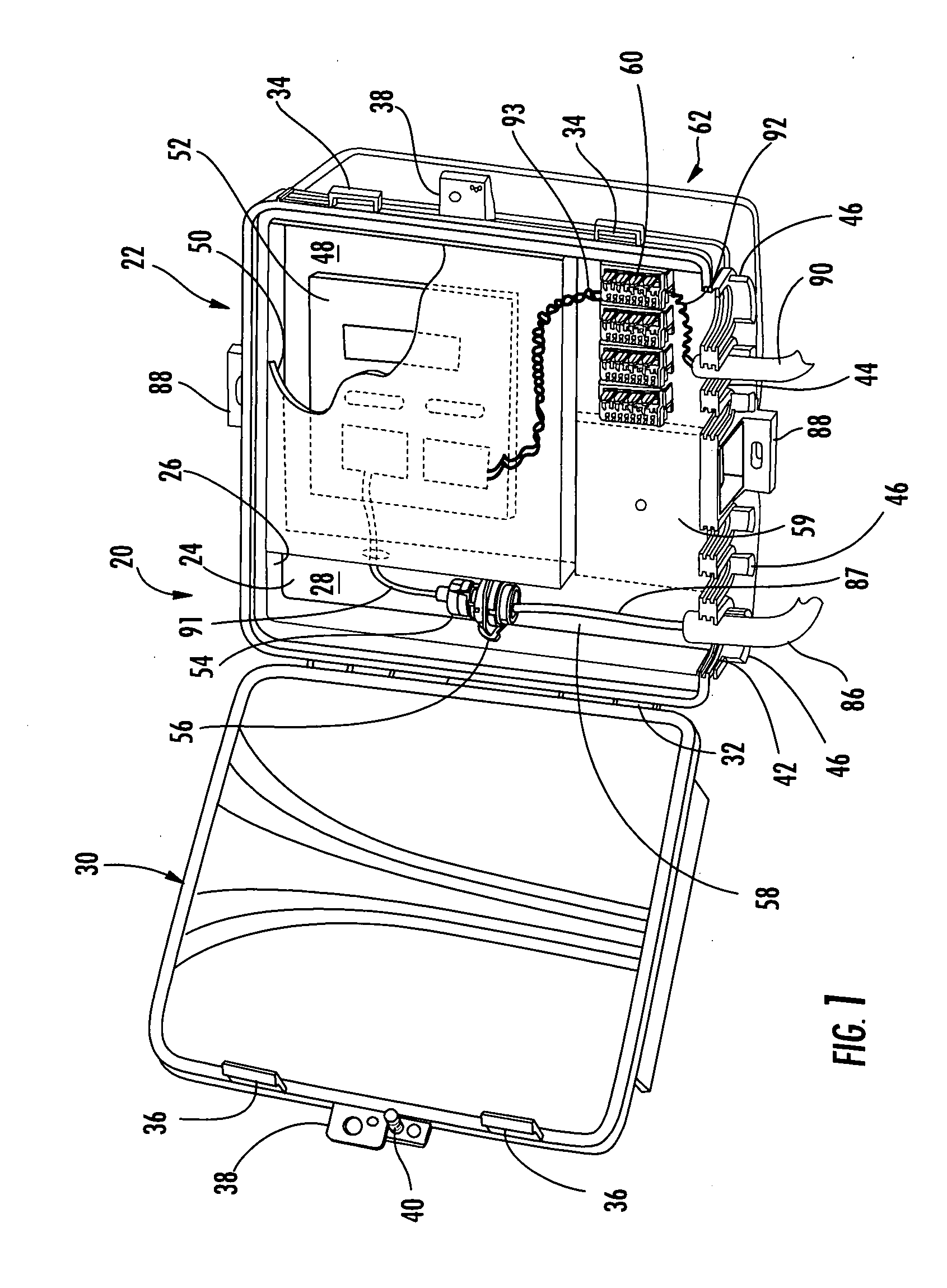
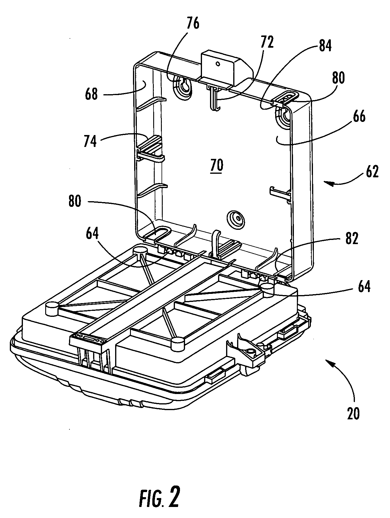
[0028]FIGS. 1-3 show an exemplary embodiment of a network ...


PUM


Abstract

A network interface device (NID) for a fiber optic communications network is provided for housing optical, electrical and/or coaxial connections and active and/or passive components. The NID includes a base and a movable panel defining a connections area and a components area. In one embodiment, a first base defines a first compartment for housing the panel and a second base defining a second compartment for storing drop cable slack, the first base being movably attached to the second base to provide access to the drop cable slack without disturbing the connections. In another embodiment, the panel defines a first compartment for optical and electrical connections and a second compartment for active and passive components, the second compartment being accessible to only the service provider. In another embodiment, the panel is removable and interchangeable to permit the service provider to upgrade the services or to expand services provided to a subscriber.

Description

BACKGROUND OF THE INVENTION [0001] 1. Field of the Invention [0002] The present invention relates generally to an enclosure for providing communications services to a subscriber premises in a fiber optic communications network. More particularly, the invention is a network interface device (NID) for connecting a network fiber optic drop cable to subscriber wiring at a subscriber premises in a fiber optic communications network. [0003] 2. Technical Background [0004] Communications service providers are currently installing fiber optic communications networks that extend to homes and businesses. Such networks are commonly referred to as to as “fiber-to-the-home (FTTH)” or “fiber-to-the-business (FTTB)” networks, and the homes and businesses are commonly referred to as “subscriber premises.” As with conventional copper communications networks, there is a need in a fiber optic network for an enclosure, referred to herein as a network interface device (NID), located at the subscriber pre...

Claims


Application Information

Patent Timeline
IPC IPC(8): G02B6/00
CPCG02B6/4447G02B6/4448G02B6/445H04Q1/028H04Q2201/10H04Q2201/16H04Q2201/804H04Q1/116H04Q1/021
Inventor NAPIORKOWSKI, JOHN J.GRUNWALD, BRAD N.KEENUM, JOHN A.VO, CHANH C.
Owner CORNING CABLE SYST LLC
Why Eureka
Try Eureka