Methods for configuring and testing fiber drop terminals

a technology of drop terminals and fiber cables, applied in the field of communication networks, can solve the problems of insufficient bandwidth for some users, increased bandwidth requirements for users, and relatively high deployment and/or maintenance costs of technologies

Inactive Publication Date: 2006-07-13
COMMSCOPE TECH LLC
View PDF39 Cites 266 Cited by
  • Summary
  • Abstract
  • Description
  • Claims
  • Application Information

AI Technical Summary

Benefits of technology

[0012] In accordance with another implementation, a method for installing a fiber drop terminal having angular coil storage is provided. The angular coil storage may maintain a manufacturer specified minimum bend radius. The method may include identifying a mounting location for the fiber drop terminal and affixing a mounting bracket to a structure suitable for supporting the fiber drop terminal. The method may include attaching the fiber drop terminal to the mounting bracket such that receptacles associated with the coil are oriented in a desired direction.

Problems solved by technology

Users may, however, demand even higher bandwidths.
The above technologies may have inadequate bandwidth for some users and / or these technologies may be relatively expensive to deploy and / or maintain.
If a fiber drop terminal has, for example, eight output receptacles, the linesman may repeat the drive to and from the drop terminal eight times. Testing fiber drop terminals using known techniques may be labor intensive and may consume excessive amounts of fuel due to the back and forth trips between the central office and fiber drop terminal locations.

Method used


Image

  • Methods for configuring and testing fiber drop terminals
  • Methods for configuring and testing fiber drop terminals
  • Methods for configuring and testing fiber drop terminals

Examples


Embodiment Construction

[0047] Reference will now be made in detail to exemplary implementations of the present invention, examples of which are illustrated in the accompanying drawings. While exemplary implementations are provided, other implementations are possible in light of the specification. As such, changes may be made to the exemplary implementations described herein without departing from the spirit and scope of the invention. The following detailed description does not limit the invention; but instead, the scope of the invention is defined by the appended claims and their equivalents. Wherever possible, the same reference numbers may be used throughout the drawings to refer to the same or like parts.

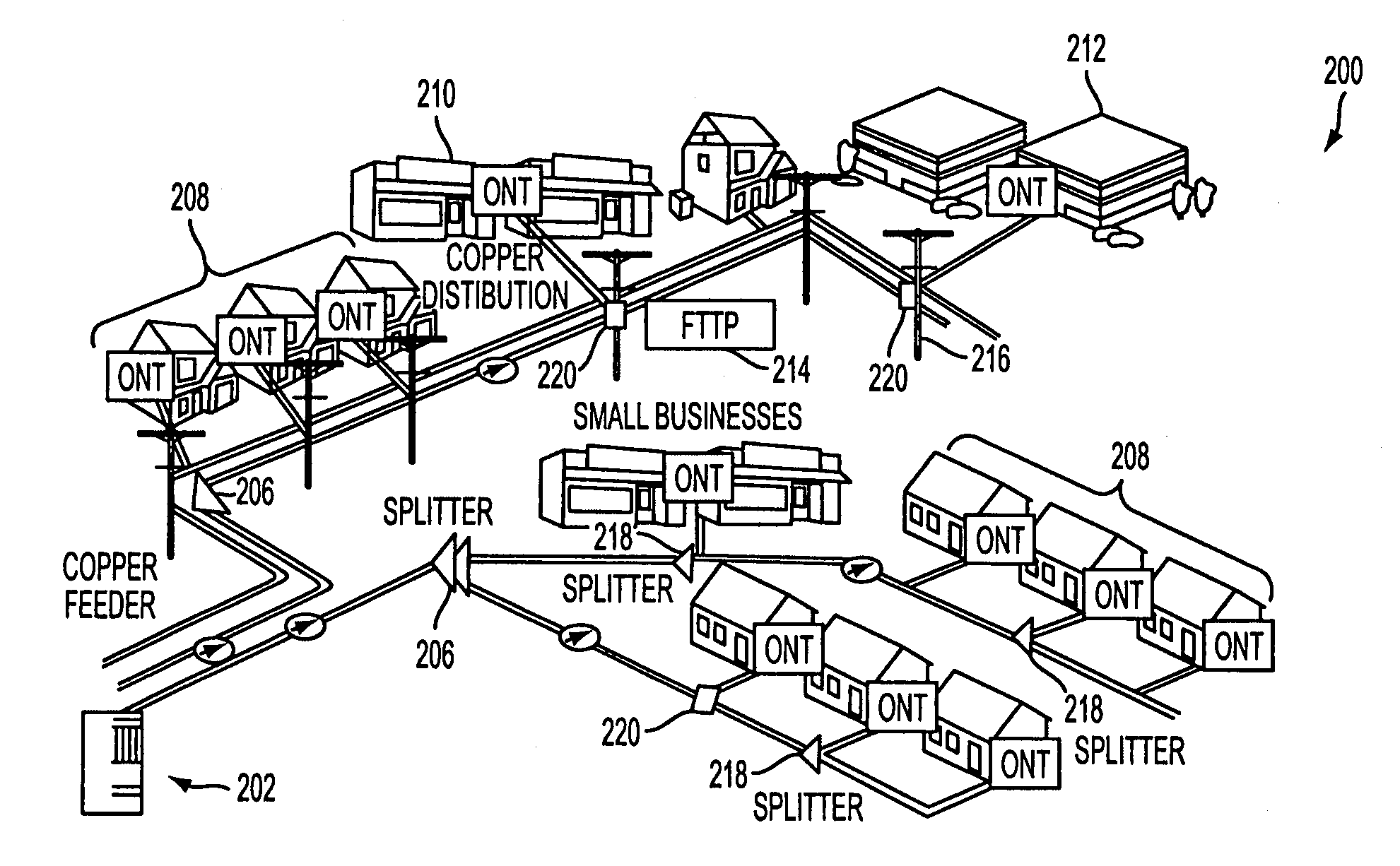
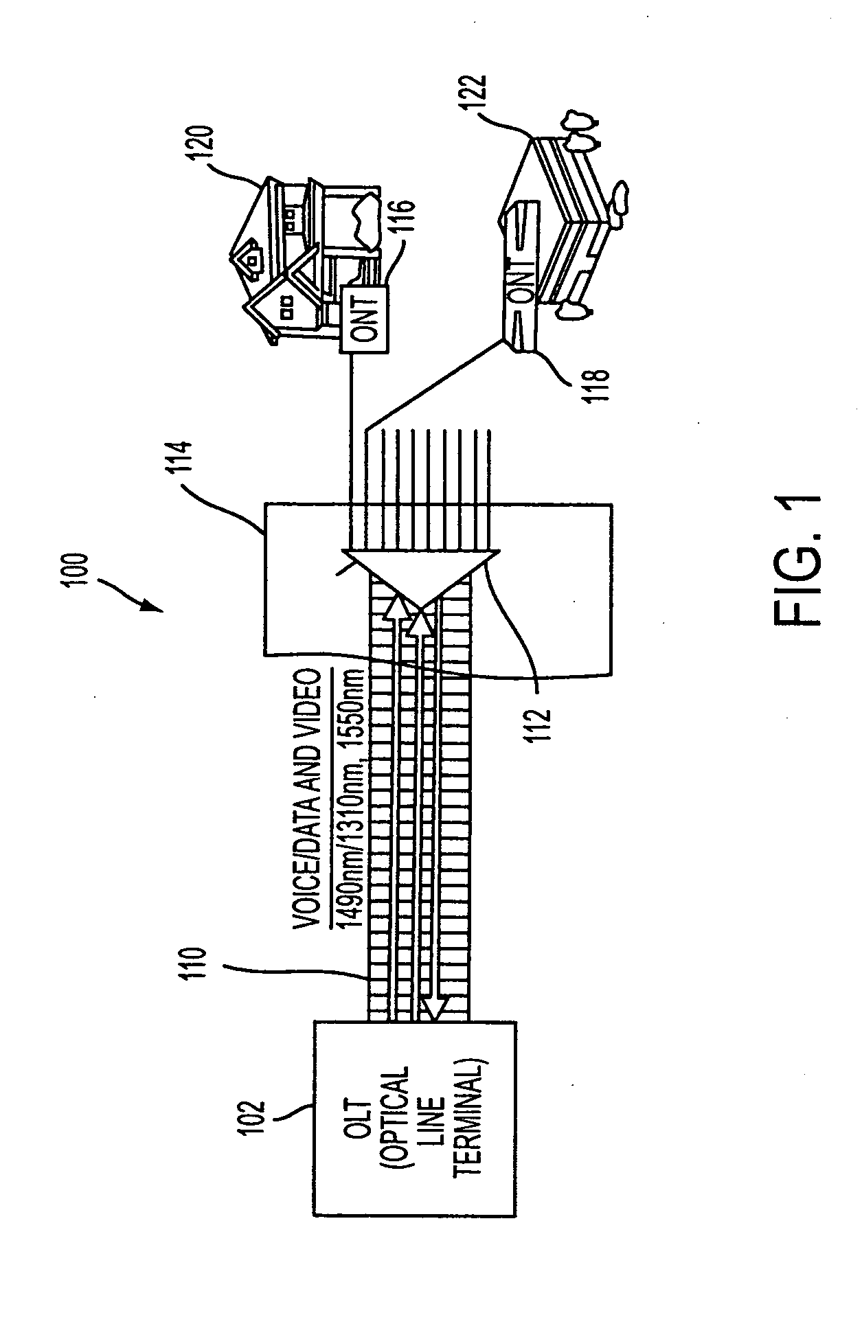
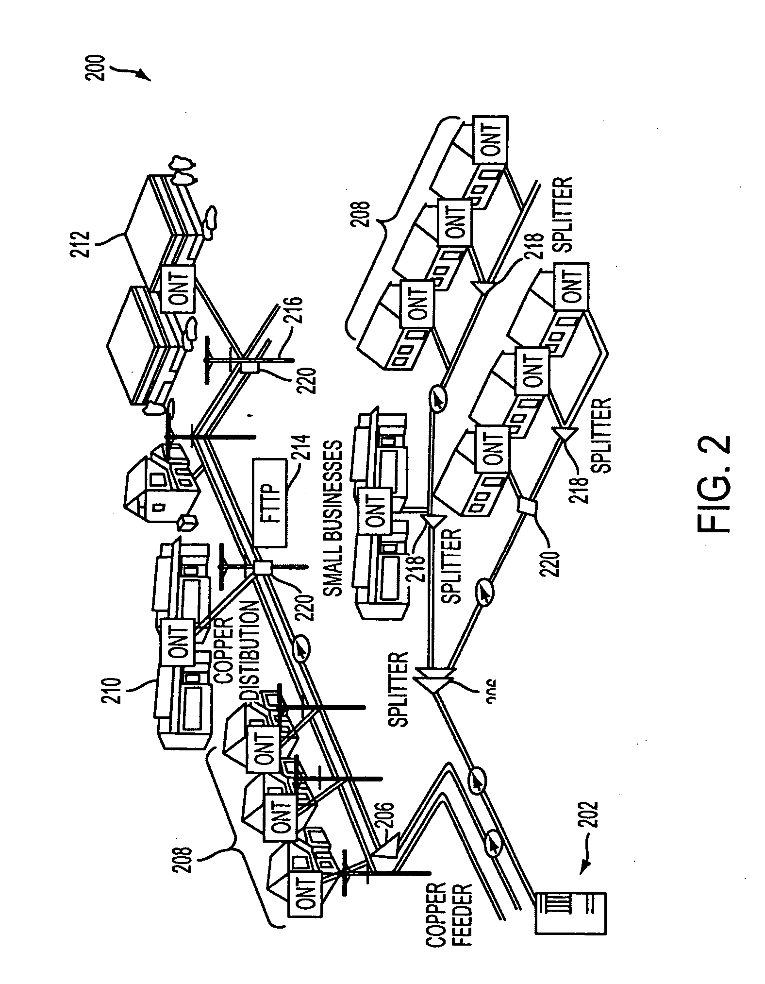
[0048]FIG. 1 illustrates a first schematic representation of an exemplary broadband access network 100 that may include PON components in an implementation consistent with the principles of the invention. Network 100 may include an optical line terminal (OLT) 102, a voice input 104, a data input 106,...


PUM


Abstract

A method for testing a fiber drop terminal from a single geographic location may include placing a signal onto a first optical fiber at the single geographic location. The first optical fiber is communicatively coupled to a first output receptacle on the fiber drop terminal. The method may also include detecting the signal via a second optical fiber at the single geographic location. The second optical fiber is communicatively coupled to a second output receptacle on the fiber drop terminal, and the second output receptacle is communicatively coupled to the first output receptacle via a loop-back assembly.

Description

RELATED APPLICATION [0001] This application claims priority under 35 U.S.C. §119(e) based on U.S. Provisional Patent Application Ser. No. 60 / 624,582, filed Nov. 3, 2004, the entire content of which is hereby incorporated herein by reference.FIELD OF THE INVENTION [0002] The present invention relates generally to communication networks and, more particularly, to methods for configuring and testing fiber drop terminals used in optical communication networks. BACKGROUND OF THE INVENTION [0003] High bandwidth communication networks are becoming more prevalent in response to user demand for enhanced communication services. High bandwidth communications may allow users to take advantage of advanced communication capabilities, such as voice-over-internet protocol (VoIP) communications, interactive gaming, delivery of high resolution video, such as high definition television (HDTV), as well as the transmission and / or reception of large data files. [0004] Communication service providers, suc...

Claims


Application Information

Patent Timeline
Patent Type & Authority Applications(United States)
IPC IPC(8): G02B6/00
CPCG02B6/3897G02B6/4441H04B10/27
Inventor REAGAN, RANDYGNIADEK, JEFFREYNOONAN, MICHAELBAREN-BOYM, MICHAEL
Owner COMMSCOPE TECH LLC
Why Eureka
Try Eureka