Eureka AIR delivers breakthrough ideas for toughest innovation challenges, trusted by R&D personnel around the world.

Bandwidth allocation method and system for data transmission in EPON

a bandwidth allocation and data transmission technology, applied in the direction of data switching networks, positive displacement liquid engines, liquid fuel engines, etc., can solve the problems of limiting the number of subscribers, inability to conventional dba algorithms cannot provide sufficient support for qos, so as to achieve efficient allocating a bandwidth for upstream transmission

Inactive Publication Date: 2006-07-13
KOREA ADVANCED INST OF SCI & TECH +1
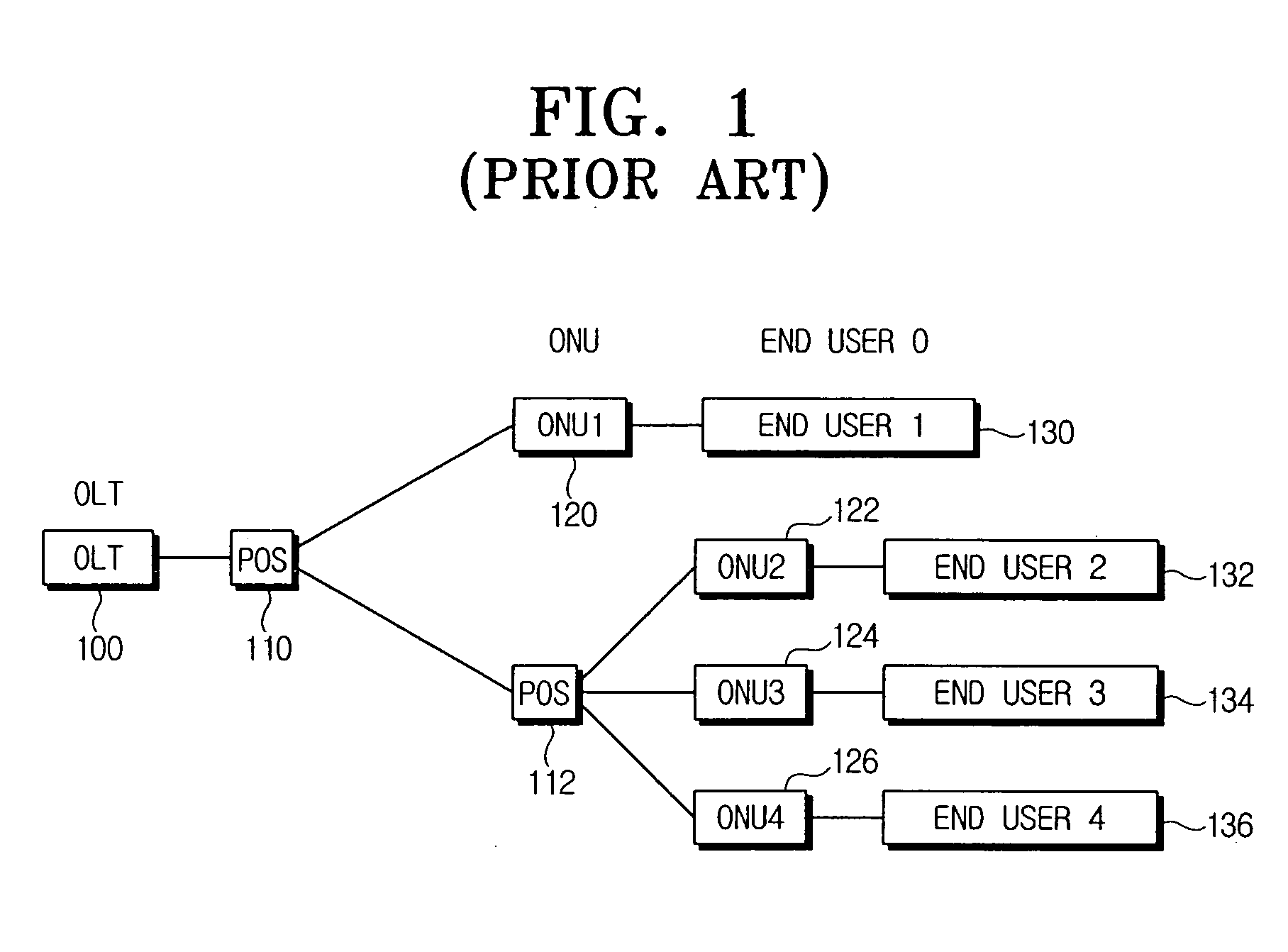
View PDF8 Cites 20 Cited by
  • Summary
  • Abstract
  • Description
  • Claims
  • Application Information

AI Technical Summary

Benefits of technology

[0014] An aspect of the present invention provides a method for efficiently allocating a bandwidth for upstream transmission by OLT in an EPON system.

Problems solved by technology

Diverse DBA mechanisms for the EPON system have been proposed in response to the QoS support, but they are incapable of providing sufficient support to satisfy the QoS requirement with respect to the diverse services.
However, the above conventional DBA algorithms cannot provide sufficient support for the QoS.
For example, the fixed window algorithm may limit the number of subscribers intending to use the services, and is incapable of actively dealing with the rapidly changing traffic due to the absence of the DBA capability.
The gated window algorithm is subject to the unfair bandwidth allocation to the plurality of the ONUs because the ONU allocates the bandwidth as requested.
In addition, the gated window algorithm lacks the ability to deal with the real-time services in an active manner.
In other words, while the gated window algorithm can maximize the efficiency in view of the network operator, the QoS is not provided to some satisfactory degree in view of the end user.
The limited window algorithm cannot actively handle the real-time traffic variation due to the limited bandwidth since the maximum bandwidth available to the ONUs is restricted.
The credit window algorithm allocates the extra bandwidth to the ONU in order to actively cope with the real-time traffic variation, but may allocate unnecessary bandwidth amount even if the amount of the requested bandwidth is less.

Method used


Image

  • Bandwidth allocation method and system for data transmission in EPON
  • Bandwidth allocation method and system for data transmission in EPON
  • Bandwidth allocation method and system for data transmission in EPON

Examples


Embodiment Construction

[0027] Certain exemplary embodiments of the present invention will now be described in greater detail with reference to the accompanying drawings.

[0028] In the following description, same drawing reference numerals are used for the same elements even in different drawings. The matters defined in the description, such as detailed construction and element descriptions, are provided to assist in a comprehensive understanding of the invention. Also, well-known functions or constructions are not described in detail since they would obscure the invention in unnecessary detail.

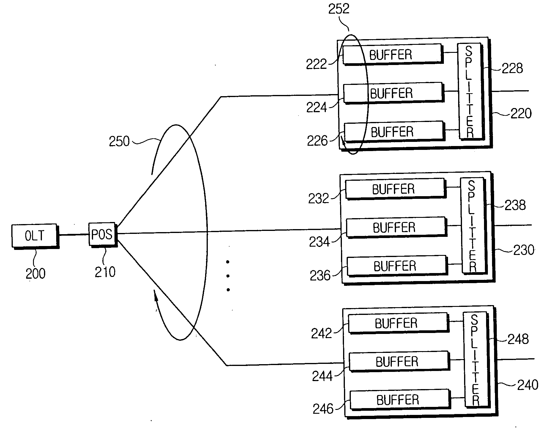
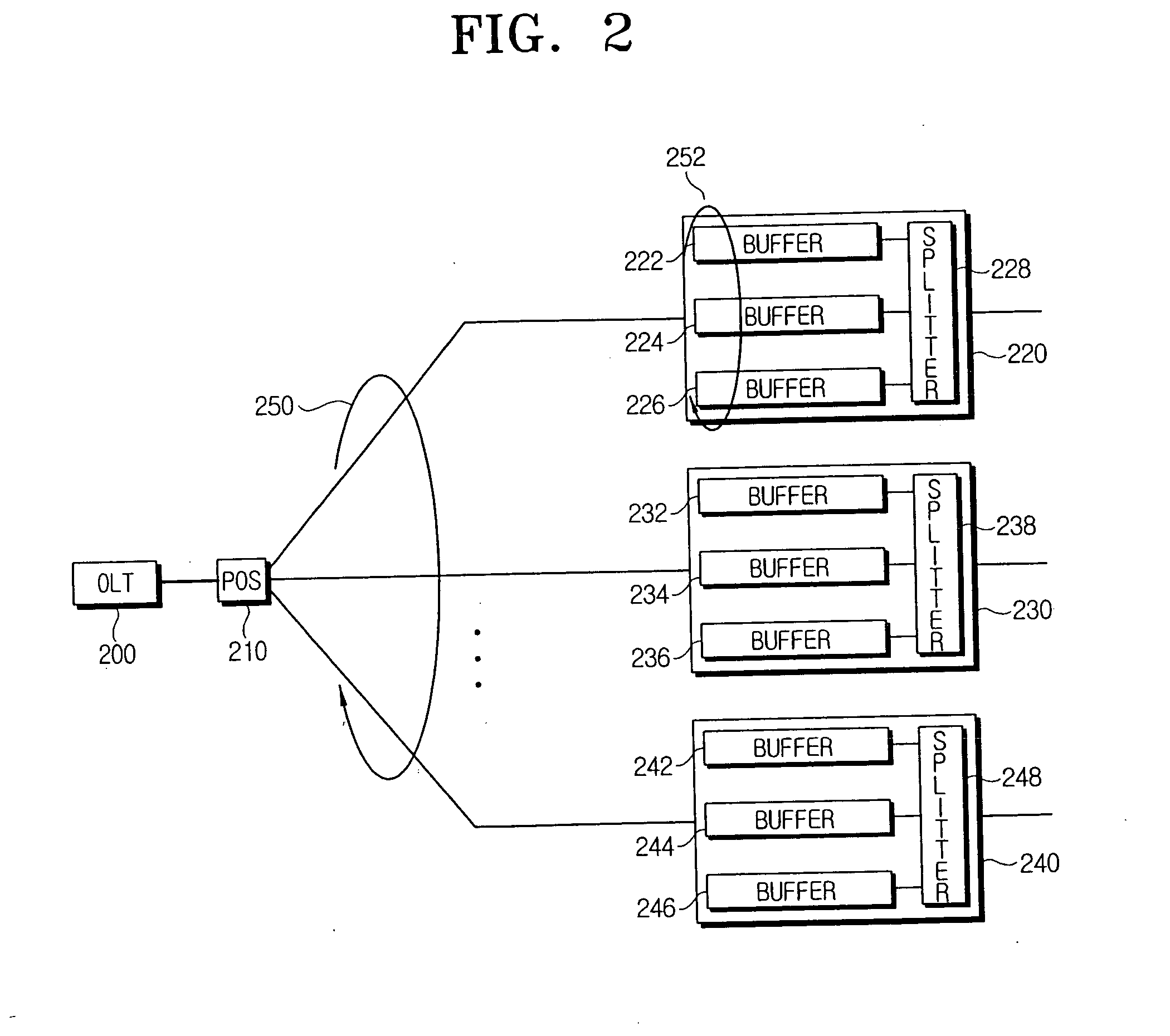
[0029] A variable transmission window algorithm according to an exemplary embodiment of the present invention can provide diverse service quality, as compared with the conventional algorithms, and actively cope with rapid changes of the traffic. The variable transmission window algorithm divides the traffic to be transmitted into at least two groups according to the characteristics of the traffic. Hereinafter, desc...


PUM


Abstract

A method for efficiently allocating a bandwidth at an optical line terminal (OLT) for upstream transmission in an Ethernet passive optical network (EPON) system. An optical network unit (ONU) divides data to be transmitted into at least two groups that include a group with a constant bit rate (CBR) and a group with a variable bit rate (VBR), and requests a required bandwidth for each of the divided groups. The OLT allocates the requested bandwidth to the group with the CBR within a first bandwidth among an allocated bandwidth including the first bandwidth and a second bandwidth. The ONU transmits data using bandwidth allocated to the divided groups by the OLT.

Description

CROSS-REFERENCE TO RELATED APPLICATIONS [0001] This application claims priority from Korean Patent Application No. 2005-2895 filed on Jan. 12, 2005 in the Korean Intellectual Property Office, the entire disclosure of which is incorporated herein by reference. BACKGROUND OF THE INVENTION [0002] 1. Field of The Invention [0003] Methods and systems consistent with the present invention relate generally to an Ethernet passive optical network (EPON), and more particularly, to efficiently distributing an upstream transmission bandwidth in an EPON architecture. [0004] 2. Description of The Related Art [0005] To establish subscriber networks from a central office (CO) to buildings or home, various network architectures have been suggested such as x-Digital Subscriber Line (xDSL), Hybrid Fiber Coax (HFC), fiber-to-the-building (FTTB), fiber-to-the-curb (FTTC), fiber-to-the-home (FTTH), and the like. Among these architectures, the deployment of the FTTx (x=B, C, H) can be divided into an acti...

Claims


Application Information

Patent Timeline
IPC IPC(8): H04J14/00
CPCH04B10/27H04L12/5695H04L47/805H04L47/828H04Q11/0067H04Q2011/0064H04L47/70F04B39/0022F04B53/147F04B39/0094
Inventor RYU, HYUN-SURKYOO, MYUNG-SIKKANG, MIN-HO
Owner KOREA ADVANCED INST OF SCI & TECH
Why Eureka
Eureka Blog
Learn More