
Portable printing system

a printing system and portability technology, applied in the direction of printing, typewriters, spacing mechanisms, etc., can solve the problems of increasing the number of electronic components that could possibly fail, introducing the possibility of user error, and increasing the cost of manufacture, so as to achieve convenient use

Inactive Publication Date: 2006-07-13
HELLERMANNTYTON CORP
View PDF29 Cites 15 Cited by
  • Summary
  • Abstract
  • Description
  • Claims
  • Application Information

AI Technical Summary

Benefits of technology

The system simplifies label design and printing, reduces user error, and minimizes waste while maintaining superior print quality across various label materials, enhancing operational efficiency and cost-effectiveness.

Problems solved by technology

Although this provides the printer with the appropriate specifications to properly print the label, it also introduces the possibility of user error.
This approach has reduced user error, but it has also increased the cost of manufacture, and increased the number of electronic components that could possibly fail.
This adds to the time and complexity of installing the label supply roll within the printer, and is compounded when a variety of label types are used.
Yet another deficiency in the art of hand held label printers is the ability to view an accurate representation of a designed label before the label is actually printed.
This deficiency in the art creates wasted labels, as a user is required to print a sample label to confirm a proper label layout.
However, reversing the ribbon feed direction can introduce ribbon wrinkling and telescoping, which leads to misprinted labels and frustrated users.
Furthermore, prior art hand-held printers have had limited download capabilities.
Previous printers have incorporated expensive interfaces to allow for data downloading or software upgrades, while other printers have had limited capabilities to communicate with a computer or an online database.
These restrictions have limited the ability of hand held printers to remain current with the latest in label options, graphic images, user languages, and software.

Method used


Image

  • Portable printing system
  • Portable printing system
  • Portable printing system

Examples


Embodiment Construction

[0043] Although the disclosure hereof is detailed and exact to enable those skilled in the art to practice the invention, the physical embodiments herein disclosed merely exemplify the invention which may be embodied in other specific structure. While the preferred embodiment has been described, the details may be changed without departing from the invention, which is defined by the claims.

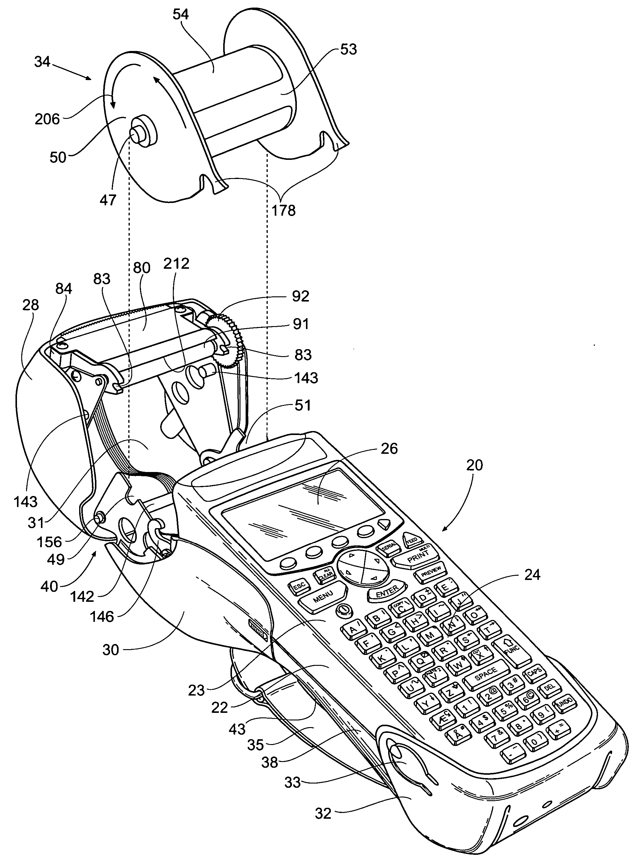
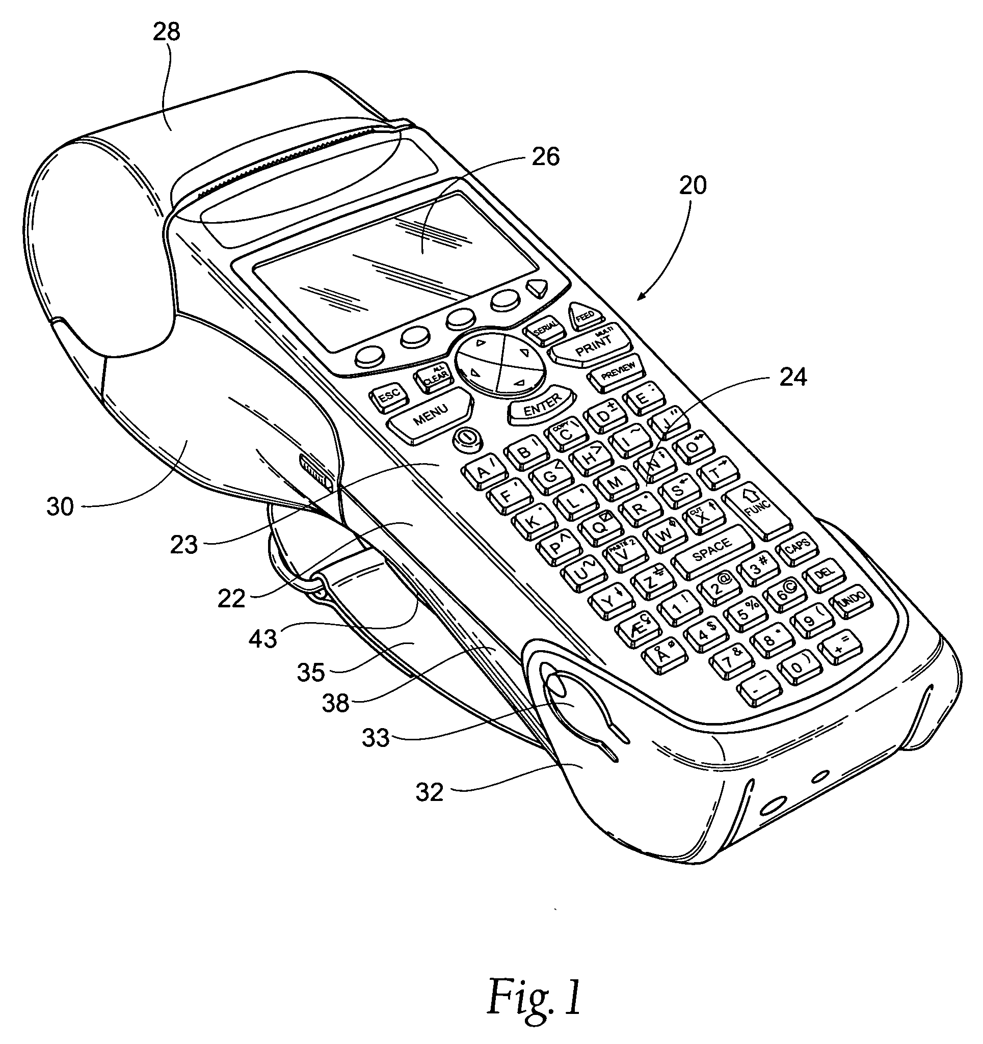
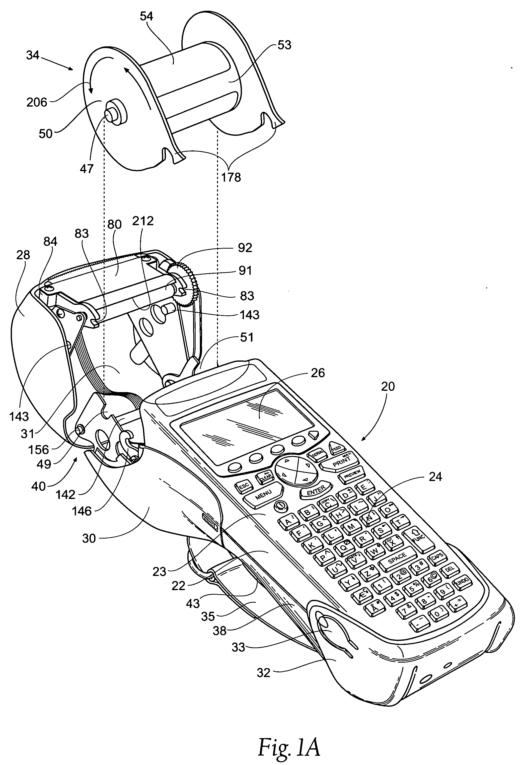
[0044] Referring to the drawings, wherein like numerals represent like parts throughout the views, there is generally designated at 20 an ergonomically designed, hand held portable printing system according to the present invention. As seen particularly in FIGS. 1 and 2, the printing system 20 includes an upper housing 22 and a lower housing 38.

[0045] The upper housing 22 supports a keyboard 24 on its front face and a graphic display 26 laterally spaced from the keyboard 24. The unique alphanumeric keyboard 24 is preferably composed of an integrally formed, continuous elastomer membrane. This co...


PUM


Abstract

A portable label printing system for printing on a variety of materials is disclosed. A retractable platen roller cooperates with a self-aligning print head in three planes cooperates for proper label printing registration. A display screen allows the user to view precisely what the actual label and associated indicia will look like when printed on a selected label. In addition, the printing system includes an optical sensor positioned to sense data marks on the backside of a label, located on a label supply roll, allowing the printing system to identify the label specifications and make necessary adjustments to affect print quality. Reverse feed of the label supply roll is possible. The label printing system further comprises a communication port for cooperation with various devices, such as online databases and computers.

Description

RELATED APPLICATION [0001] This application is a divisional of co-pending U.S. patent application Ser. No. 10 / 860,912, filed 4 Jun. 2004, which claims the benefit of Provisional U.S. Patent Application Ser. No. 60 / 475,659, filed 4 Jun. 2003.BACKGROUND OF THE INVENTION [0002] 1. Field of the Invention [0003] This invention relates to the art of hand-held printing systems and more particularly to a portable thermal label printing system that has improved functionality for ease of operation and print quality. [0004] 2. Brief Description of the Prior Art [0005] There has been previously disclosed a number of hand-held printers and various stationary printers with the ability to print indicia on labels. Examples of such hand-held label printers have been disclosed in U.S. Pat. Nos. 4,807,177, Ward; 5,918,989, Stout, Jr. et al.; 5,951,177, Schanke et al.; and 6,113,293, Schanke et al. The electronic apparatus of the types disclosed above commonly include a general combination of elements ...

Claims


Application Information

Patent Timeline
Patent Type & Authority Applications(United States)
IPC IPC(8): B41J3/36B41J3/407B41J11/00B41J15/04
CPCB41J3/4075B41J11/009B41J15/042Y10S400/902
Inventor FRIES, TODDDYER, EDWARD P.LYSKAWA, DONALD V.
Owner HELLERMANNTYTON CORP
Learn More