Modular floating dock with inflatable pontoons

a floating dock and pontoon technology, applied in the field of floating docks, can solve the problems of floating dock technology, difficult or impractical delivery, and difficulty in securing a fixed dock, and achieve the effect of simple modular configuration

Inactive Publication Date: 2006-07-13
BASTA SAMUEL T
View PDF13 Cites 33 Cited by
  • Summary
  • Abstract
  • Description
  • Claims
  • Application Information

AI Technical Summary

Benefits of technology

[0010] What is needed is a floating dock that offers the advantage of simple modular configuration but that does not have the disadvantages associated with large rigid pontoons.

Problems solved by technology

Floating upon the body of water, such docks provide convenient mooring at a constant level above the surface, in contrast with fixed docks whose use may at times be rendered difficult or impractical due to varying seasonal depth of the body of water.
Floating docks can provide mooring in bodies of water in which securing a fixed dock is difficult, as in deep muddy or sandy bottoms.
However, floating dock technology has heretofore suffered from a number of shortcomings as well.
First, because a commensurate volume of water must be displaced for the dock to float, the required dimensions for floating dock pontoons present significant manufacturing costs if rigid pontoons are employed.
To provide even a minimal amount of buoyancy such as 1000 pounds, the pontoons must displace approximately 125 gallons of water, often requiring expensive tooling to produce rigid pontoons of such size.
Similarly, Rueckert's dock cited above provides buoyancy by large polyethylene articles that are created in a rotating mold, at considerable cost.
Even if floating dock pontoons are manufactured sectionally as float drums, as described in U.S. Pat. No. 4,974,538 to Meriweather, manufacturing rigid pontoons of such large displacement entails considerable difficulty and cost.
Second, shipment of large rigid pontoons to the site where the floating dock is to be assembled and deployed entails additional difficulty and cost.
Even when the pontoons themselves may not be costly, such as the steel tanks employed in the dock described in U.S. Pat. No. 4,979,453 to Sloan et al., their size of necessity results in significant shipping costs.
Third, assembly and disassembly of a floating dock, whether for installation, maintenance or relocation, is more complicated when large rigid pontoons are involved, because of the difficulty in maneuvering pontoons of larger dimensions.
However, heretofore docks with inflatable pontoons have not provided the flexibility of configuration found in prior art modular floating docks.

Method used


Image

  • Modular floating dock with inflatable pontoons
  • Modular floating dock with inflatable pontoons
  • Modular floating dock with inflatable pontoons

Examples


Embodiment Construction

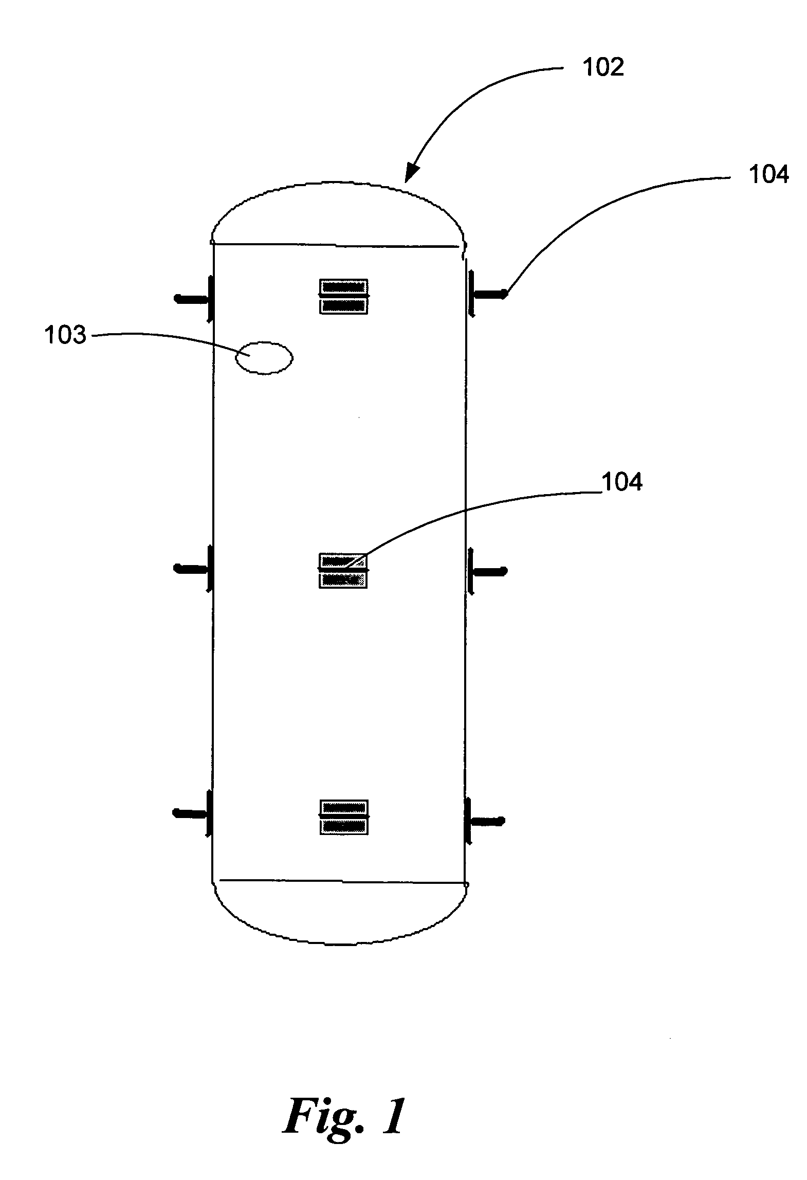
[0018] Referring to FIG. 1, illustrated is an inflatable pontoon module according to the present invention. Pontoon 102 comprises a tube of polymer coated fabric material, with closed ends of the same or similar material, made airtight. Pontoon 102 is further fitted with valve 103 for inflation and deflation in the manner of inflatable rafts of rubberized fabric, well known to those in the art. In preferred embodiments, pontoon 102 comprises a plurality of chambered sections, so that in the event of a rupture, the pontoon will still retain partial buoyancy.

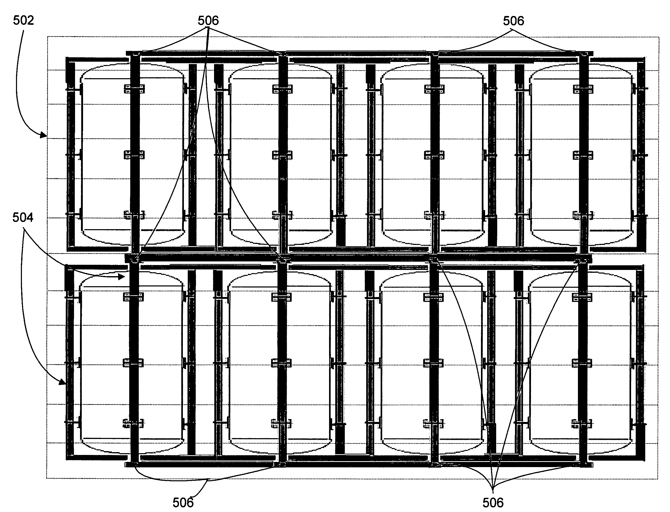
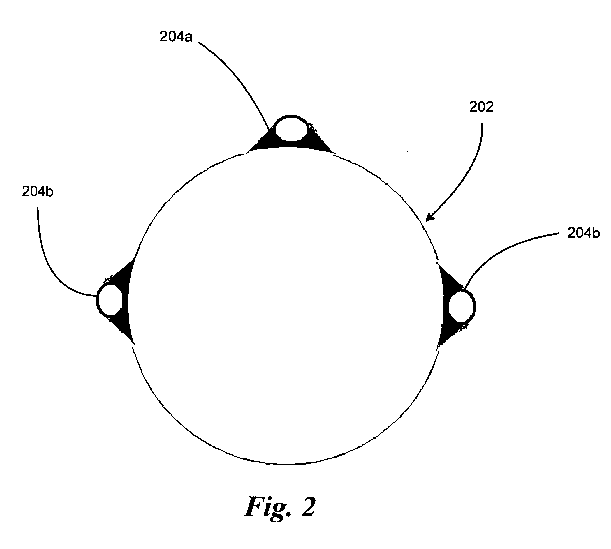
[0019] Affixed to pontoon 102 are a number of annular components 104, arranged in groups to form lines along the surface of pontoon 102 parallel to the main axis of the pontoon, as will be described in greater detail in the following passages in reference to the other figures in this specification.

[0020] Annular components 104 are comprised of a relatively rigid and durable material, such as metal or plastic, suitable for prolon...


PUM


Abstract

A modular buoyant support apparatus is comprised of buoyant support modules of inflatable pontoons. The pontoons comprise inflatable tubular chambers, typically fabricated of polymer coated fabric sheet material. A buoyant support module comprises a rigid frame connected to an inflatable pontoon. A means is provided to interconnect buoyant support modules to form a modular buoyant support apparatus of varied support area and configuration. Means are provided to attach an appropriately configured dock surface to the modular buoyant support apparatus.

Description

CROSS-REFERENCE TO RELATED APPLICATION [0001] This application claims the benefit under Title 35, United States Code, Section 119(a) of U.S. application Ser. No. 60 / 660,287, filed Mar. 10, 2005, which is a continuation-in-part of U.S. application Ser. No. 10 / 890,882, filed Apr. 13, 2004, which is a continuation-in-part of U.S. application Ser. No. 10 / 816,992, filed Apr. 2, 2004, which is a continuation of PCT Application No. PCT / US01 / 46253, filed Oct. 23, 2001, which is a continuation-in-part of U.S. application Ser. No. 09 / 316,928, filed May 21, 1999, and claims priority from U.S. provisional application No. 60 / 086,428, filed May 22, 1998, entitled LOW PROFILE LIFT FOR WATERCRAFT.BACKGROUND OF THE INVENTION [0002] 1. Field of the Invention [0003] This invention relates to buoyant platforms which have provisions for berthing of boats thereto or thereon, as floating docks, and more specifically to improvements thereon as modular structures. [0004] 2. Description of the Related Art [0...

Claims


Application Information

Patent Timeline
Patent Type & Authority Applications(United States)
IPC IPC(8): B63C1/00
CPCB63B3/06B63B3/08B63B7/082B63B35/34B63B35/38B63C1/02
Inventor BASTA, SAMUEL T.
Owner BASTA SAMUEL T
Why Eureka
Try Eureka