Control system for battery powered heating device

a control system and heating device technology, applied in process control, soldering apparatus, instruments, etc., can solve the problems of not providing control systems to minimize power utilization and extend battery life, and limited performan

Active Publication Date: 2006-07-20
HAKKO CO LTD
View PDF99 Cites 22 Cited by
  • Summary
  • Abstract
  • Description
  • Claims
  • Application Information

AI Technical Summary

Problems solved by technology

However, there are a few battery powered soldering devices that are available though their performance is somewhat limited.
While the devices according to the prior art may be able to provide cordless soldering capabilities, they do not provide control systems to minimize the amount of power utilization to extend the battery life.

Method used


Image

  • Control system for battery powered heating device
  • Control system for battery powered heating device
  • Control system for battery powered heating device

Examples


Embodiment Construction

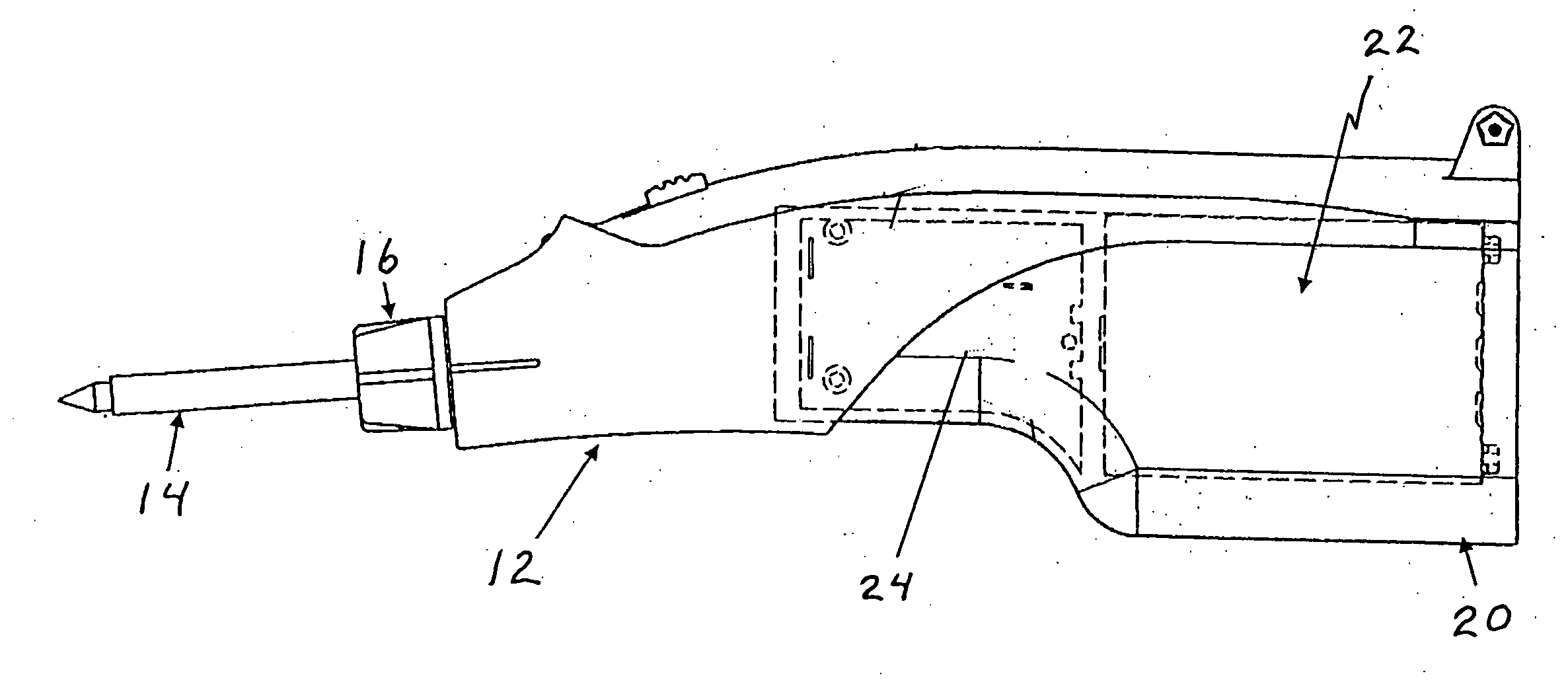
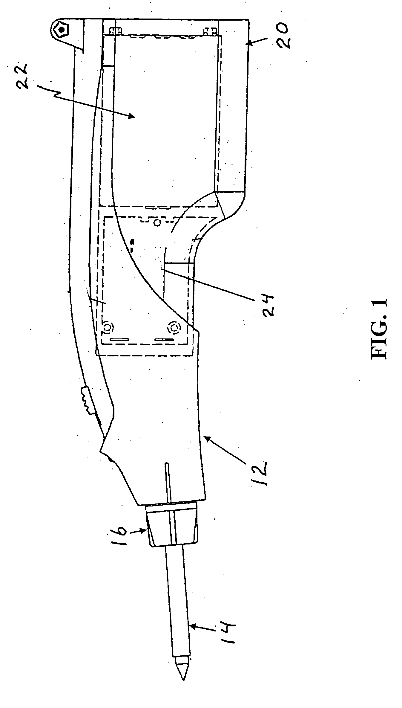
[0017]FIG. 1 depicts a side view of a battery powered heating device 10 according to the present invention. The heating device 10 includes a handle 12 onto which a cartridge heating tip 14 is mounted and secured with a securing nut 16. The heating device preferably includes a removable battery pack and control system 20 which may be removed for charging or replacement of the battery or substitution of a charged battery pack. Structural details of an exemplary heating device in a soldering iron configuration are disclosed in the application Ser. No. 10 / 892,780 incorporated herein by reference. Briefly, the battery cartridge 20 includes a battery 22 and a circuit board 24. The circuit board 24 includes the primary components to connect to the battery, control the output of power and transmit power to the heating element of the cartridge heating tip 14. The cartridge heating tip 14 generally includes a coil resistance heating element to heat an iron tip.

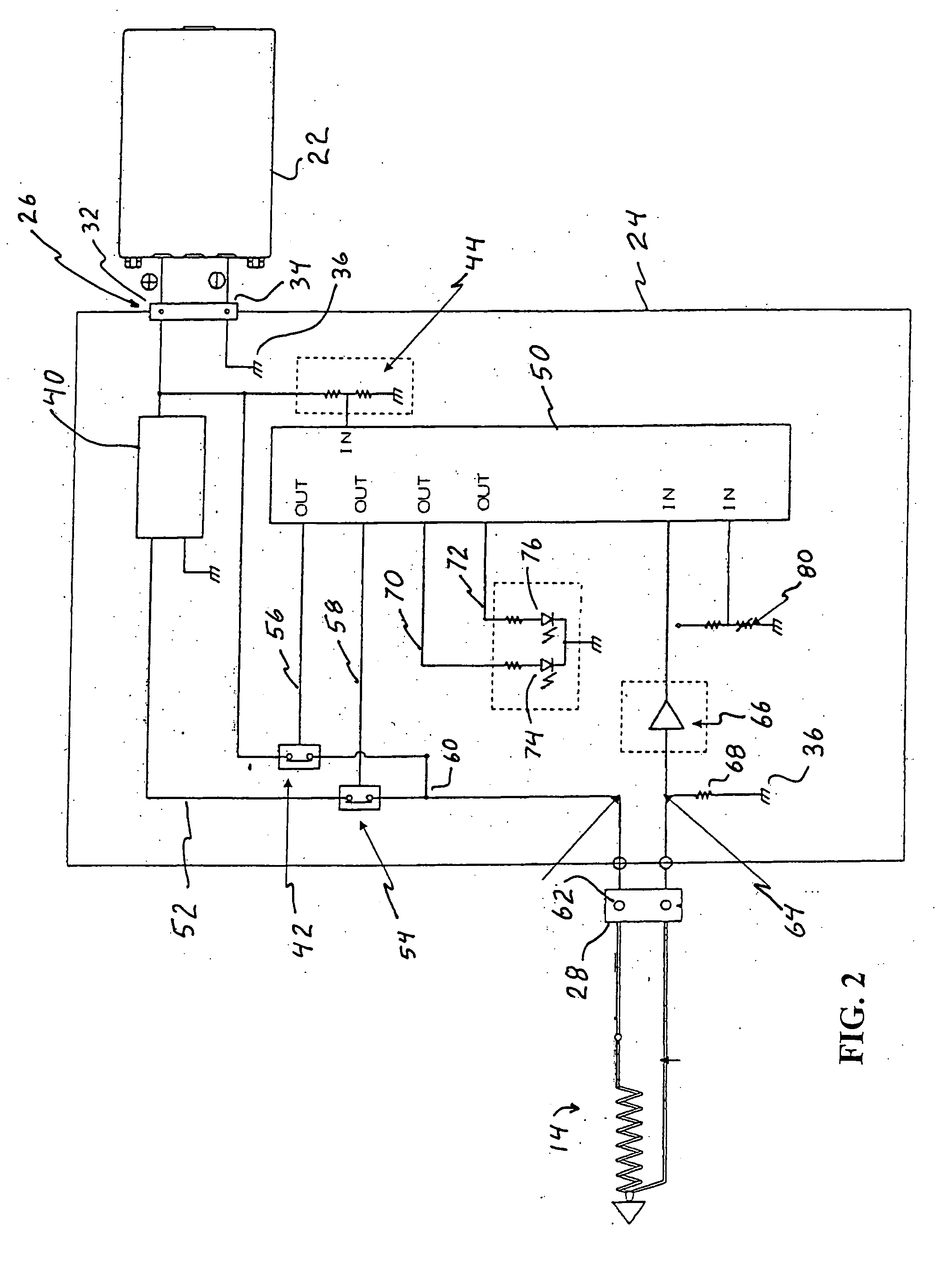
[0018]FIG. 2 depicts a schemati...


PUM


Abstract

A control system and method of controlling a battery powered heating device such as a soldering or desoldering tool that includes a control circuit to control the delivery of power to a cartridge heating tip and to cycle the power to the cartridge heating tip during times of no use so as to minimize the amount of power expended to maintain the device in a ready or usable state.

Description

BACKGROUND OF THE INVENTION [0001] 1. Field of the Invention [0002] The present invention is directed to the field of battery powered heating devices such as battery powered soldering irons. An exemplary version of such a device is disclosed in U.S. Patent Application Ser. No. 10 / 892,780, filed on Jul. 15, 2004, titled: “Soldering Device with Cartridge Type Battery Pack”, hereby incorporated by reference. The present invention is more particularly directed to a control system to monitor and control the delivery of power to the heating device so as to provide the power necessary for utilization of the device yet reduce or minimize the battery drain and any unnecessary expenditure of power, and thereby maximize the battery life. [0003] 2. General Background and State of the Art [0004] Soldering irons are used to make secure electrical connections by melting solder and allowing the solder to bond between two electrical devices such as wires and contact points of a circuit. A number of ...

Claims


Application Information

Patent Timeline
Patent Type & Authority Applications(United States)
IPC IPC(8): H05B3/02H05B1/00H05B11/00
CPCB23K3/0323B23K3/033G05D23/2401G05D23/2422G05D23/1917
Inventor MIYAZAKI, MITSUHIKOISHIHARA, TOSHINOBUTAKEUCHI, HITOSHI
Owner HAKKO CO LTD
Why Eureka
Try Eureka