Image pickup device, its control method, and camera

a pickup device and image technology, applied in the field of image pickup devices, its control methods, and cameras, can solve the problems of asymmetrical structure, loss of accumulation time of floating diffusion region, and all the pieces of information of carriers which have flowed into the floating diffusion region for a period,

Inactive Publication Date: 2006-07-20
CANON KK
View PDF35 Cites 127 Cited by
  • Summary
  • Abstract
  • Description
  • Claims
  • Application Information

AI Technical Summary

Benefits of technology

[0009] An image pickup device according to the present invention includes: a photoelectric conversion unit generating carriers by photoelectric conversion to accumulate the carriers; a transfer transistor for transferring the carriers of the photoelectric conversion unit; a floating diffusion region into which the carriers are transferred by the transfer transistor; a transfer gate control unit controlling a gate voltage of the transfer tran...

Problems solved by technology

However, all of the pieces of information of carriers which have flowed from the photodiode into the floating diffusion region for a period from the start of the accumulation time of the photodiode to the start of the accumulation time of the floating diffusion region are lost.
Because dispersion arises in each ...

Method used


Image

  • Image pickup device, its control method, and camera
  • Image pickup device, its control method, and camera
  • Image pickup device, its control method, and camera

Examples


first embodiment

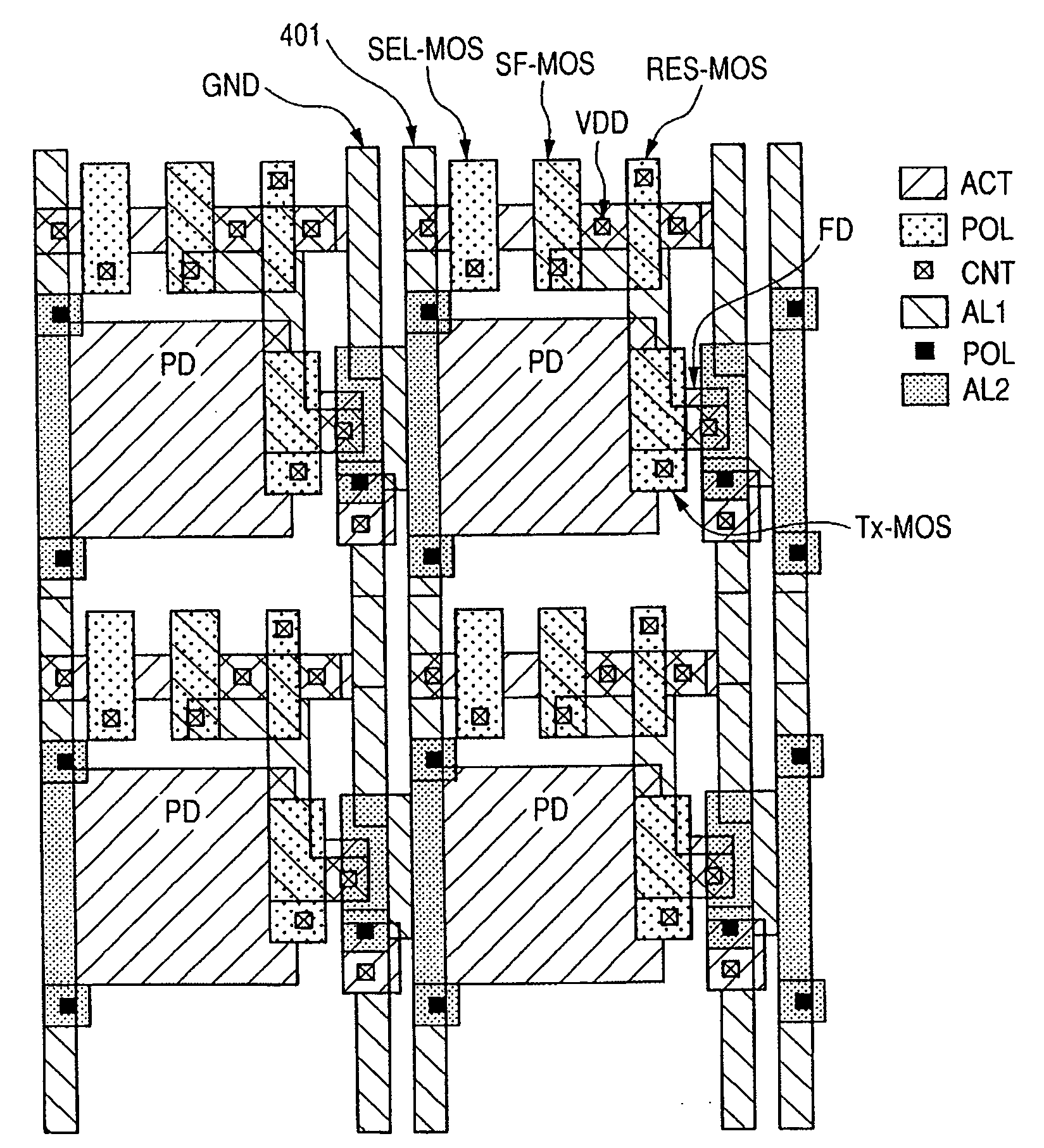
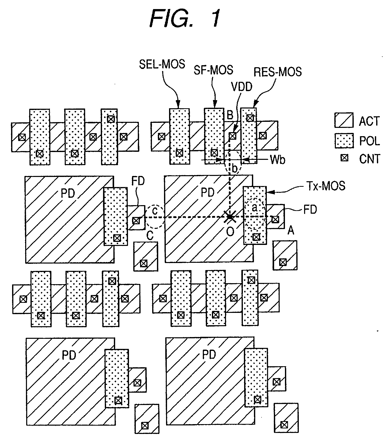
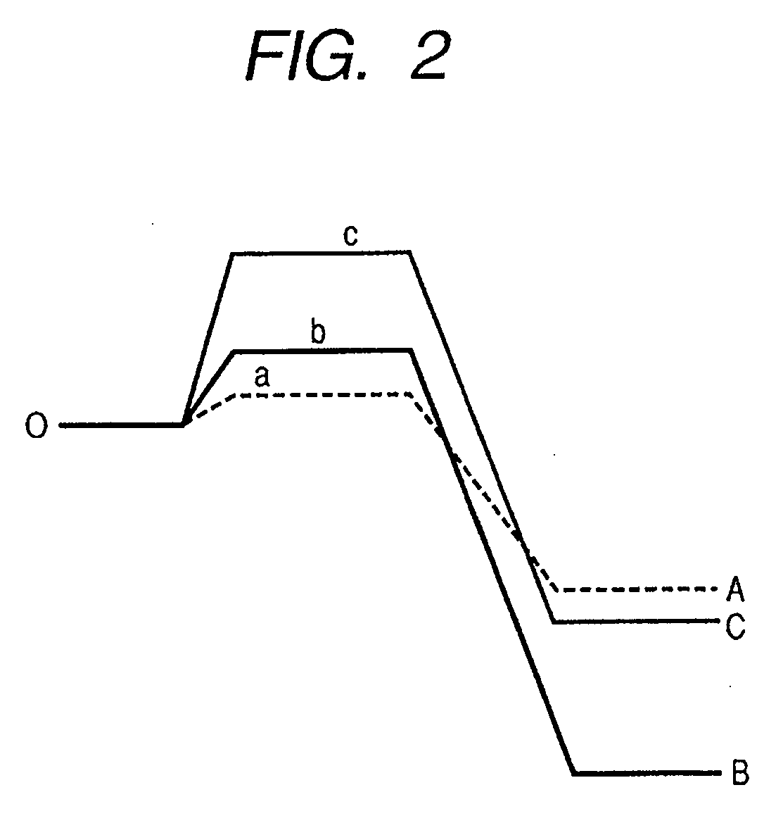
[0023]FIG. 1 is a layout chart showing a configuration example of pixel units of an image pickup device according to a first embodiment of the present invention, and FIG. 2 is a potential diagram of the cross sections taken along an O-A line, an O-B line and an O-C line in FIG. 1 during a carrier storing period. In the following, an n-channel MOS field effect transistor is simply referred to as a MOS transistor. In the image pickup device, plural pixels are two-dimensionally arranged. FIG. 1 is a plan view showing arranged four pixels as an example. One pixel includes a transfer MOS transistor Tx-MOS and a reset MOS transistor RES-MOS. Furthermore, the pixel includes a source follower MOS transistor SF-MOS and a selection MOS transistor SEL-MOS. A photo-diode PD and a floating diffusion region FD correspond to a source and a drain of the transfer MOS transistor Tx-MOS, respectively. A drain B of the transistor RES-MOS is connected to a fixed power source voltage VDD.

[0024] The phot...

second embodiment

[0058]FIG. 6 is a block diagram showing a configuration example of a still video camera according to a second embodiment of the present invention. Based on FIG. 6, an example at the time of applying the image pickup device of the first embodiment to the still video camera is described in full detail. An image pickup device 54 and a circuit 55 processing an image pickup signal correspond to the above image pickup device.

[0059] In FIG. 6, a reference numeral 51 denotes a barrier used as a protector and a main switch of a lens commonly. A reference numeral 52 denotes a lens focusing an optical image of a subject on the image pickup device 54. A reference numeral 53 denotes a diaphragm and shutter for changing the quantity of the light having passed through the lens 52. And the reference numeral 54 denotes the image pickup device for capturing the subject focused by the lens 52 as an image signal. The reference numeral 55 denotes the circuit for processing an image pickup signal which ...

third embodiment

[0064]FIG. 7 is a block diagram showing a configuration example of a video camera according to a third embodiment of the present invention. Based on FIG. 7, an embodiment in the case where the image pickup device of the first embodiment is applied to a video camera is described in full detail.

[0065] A reference numeral 1 denotes a photographing lens equipped with a focus lens 1A for performing a focus adjustment, a zoom lens 1B performing a zoom operation, and a lens 1C for image formation. A reference numeral 2 denotes a diaphragm and shutter. A reference numeral 3 denotes an image pickup device performing the photoelectric conversion of a subject image formed as an image on the image pickup surface thereof to convert the subject image into an electric image pickup signal. A reference numeral 4 denotes a sample hold circuit (S / H circuit) which performs the sample hold of the image pickup signal output from the image pickup device 3 and further amplifies the level. The S / H circuit ...


PUM


Abstract

An image pickup device, wherein a part of the carriers overflowing from the photoelectric conversion unit for a period of photoelectrically generating and accumulating the carriers may be flowed into the floating diffusion region, and a pixel signal generating unit generating a pixel signal according to the carriers stored in the photoelectric conversion unit and the carriers having overflowed into the floating diffusion region, is provided. The expansion of a dynamic range and the improvement of an image quality can be provided by controlling a ratio of the carriers flowing into the floating diffusion region to the carriers overflowing from such a photoelectric conversion unit at high accuracy.

Description

BACKGROUND OF THE INVENTION [0001] 1. Field of the Invention [0002] The present invention relates to an image pickup device, its control method, and a camera. [0003] 2. Related Background Art [0004] The specification of U.S. Pat. No. 6,307,195 discloses an image pickup device in which carriers having overflowed from a photodiode while photo carriers are being accumulated overflow into a floating diffusion (FD) region through a transfer gate (TG). In the image pickup device, a part of the carriers having flowed into the floating diffusion region is discarded for expanding the dynamic range of the device. Accordingly, the accumulation time of the floating diffusion region is set to be shorter than the accumulation time of the photodiode. In the configuration described above, it is stated that the dynamic range can be expanded by shortening the accumulation time of the floating diffusion region. However, all of the pieces of information of carriers which have flowed from the photodiode...

Claims


Application Information

Patent Timeline
IPC IPC(8): H01L31/113H04N5/335H04N5/355H04N5/374
CPCH04N3/155H01L27/14603H04N5/235H04N5/2355H04N23/70H04N23/741H04N25/587H04N25/583H04N25/59H04N25/621H04N25/75
Inventor OKITA, AKIRAKOIZUMI, TORUUENO, ISAMUSAKURAI, KATSUHITO
Owner CANON KK
Why Eureka
Try Eureka