Test apparatus

a test apparatus and test tube technology, applied in the direction of coupling device connection, semiconductor/solid-state device testing/measurement, instruments, etc., can solve the problems of high risk of damage to the light emission face of each connector, damage to a part of the light emission face of the connector, and the difficulty of conventionally-known connection methods in efficiently and safely connecting the connectors of a large number of optical fibers, etc., to achieve efficient and safe connection

Inactive Publication Date: 2006-07-20
ADVANTEST CORP
View PDF8 Cites 1 Cited by
  • Summary
  • Abstract
  • Description
  • Claims
  • Application Information

AI Technical Summary

Benefits of technology

[0031] The present invention enables a great number of connec...

Problems solved by technology

However, there is a problem of high risk of damaging the light emission face of each connector for connection with the optical fiber cable due to contact and so forth.
In a case of performing connection of multiple connectors at the same time for each test board, in some cases, the light emission faces of a part of the c...

Method used


Image

  • Test apparatus
  • Test apparatus
  • Test apparatus

Examples


Embodiment Construction

[0043] The present invention will now be described by way of embodiments; however, it should be understood that the following embodiments do not restrict the invention according to the Claims, and that combinations of features described in the embodiments are not necessarily indispensable to the present invention.

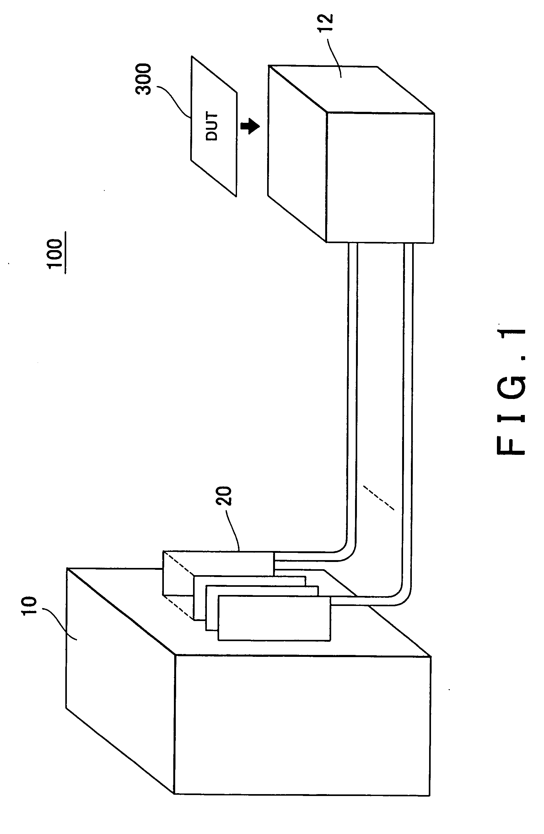
[0044]FIG. 1 is a diagram which shows an example of a test apparatus 100 according to an embodiment of the present invention. The test apparatus 100 is an apparatus for testing an electronic device 300 such as a semiconductor circuit and so forth, and includes a main frame 10, multiple cable units 20, and a test head 12. With the present example, transmission of signals between the main frame 10 and the test head 12 is performed via optical fiber cables.

[0045] The test head 12 has a function of applying a test pattern to the electronic device 300. The test head 12 may apply test patterns to multiple electronic devices 300. Specifically, the test head 12 is connected to th...


PUM


Abstract

The present invention provides a test apparatus which comprises: a test head which applies a test pattern to the electronic device; a main frame which includes multiple frame-side connectors and which supplies control signals to the test head via the frame-side connectors; and a cable unit which provides optical connection between the frame-side connectors and the test head, and which transmits the control signals to the test head. With such an arrangement, the cable unit comprises: multiple optical fiber cables which transmit the control signals; multiple unit-side connectors which are provided at the ends of the optical fiber cables, and which are provided corresponding to the multiple frame-side connectors; a unit fixing portion which fixes the cable unit to the main frame; and a connector holder which holds the unit-side connectors in a manner which enables each unit-side connector to be inserted/extracted into/from the frame-side connector independent of each other.

Description

CROSS REFERENCE TO RELATED APPLICATION [0001] This is a continuation application of PCT / JP2005 / 021690 filed on Nov. 25, 2005 which claims priority from a Japanese Patent Application No. 2004-347860 filed on Nov. 30, 2004, the contents of which are incorporated herein by reference.BACKGROUND OF THE INVENTION [0002] 1. Field of the Invention [0003] The present invention relates to a test apparatus for testing an electronic device. In particular, the present invention relates to a test apparatus which has a function of transmitting a signal using an optical fiber cable. [0004] 2. Related Art [0005] As the speed of electronic devices has increased in recent years, there is a demand for development of a test apparatus having a function of testing an electronic device at high speed. Conceived examples of such high-speed operation test apparatuses include an apparatus having a configuration in which a main frame and a test head are connected via optical fiber cables. With such an arrangeme...

Claims


Application Information

Patent Timeline
IPC IPC(8): G01R31/02
CPCG01R31/2889G01R31/26H01L22/00
Inventor ONO, ATSUSHIOKAYASU, TOSHIYUKIFUJIMOTO, AKIHIROSHIBATA, MASASHI
Owner ADVANTEST CORP
Why Eureka
Try Eureka