Steel truss girder unit lifting method used in lifting mode of single lifting point

A steel truss girder and mode technology, which is applied in the field of overall hoisting and installation of steel truss girder unit bridge positions of long-span steel structure cable-stayed bridges or suspension bridges, can solve the problems of increasing safety risks of construction operations, secondary damage to the surface of steel structures, Surface damage of steel structure panels and other problems, to achieve the effect of convenient and quick installation and dismantling, good construction effect and low cost

Pending Publication Date: 2018-12-25
CCCC SHEC SECOND ENG
View PDF0 Cites 1 Cited by
  • Summary
  • Abstract
  • Description
  • Claims
  • Application Information

AI Technical Summary

Problems solved by technology

The lifting connection method using welded lugs requires a corresponding number of lifting connection lugs to be installed on each steel truss girder. The material investment is large, the welding workload is large, and the cost is relatively high; at the same time, in the lug welding process It will inevitably cause some damage to the surface of the steel structure plate; in addition, after the installation of the steel truss girder unit, the additional welded lugs need to be cut off, which is not only time-consuming and laborious, but also increases the safety risk of the construction operation. Will cause secondary damage to the surface of the steel structure
Therefore, whether it is from the control of construction costs, the safety and reliability of construction organization, or the structural safety of the steel structure itself, the use of welded lugs has various disadvantages in all aspects.

Method used


Image

  • Steel truss girder unit lifting method used in lifting mode of single lifting point
  • Steel truss girder unit lifting method used in lifting mode of single lifting point
  • Steel truss girder unit lifting method used in lifting mode of single lifting point

Examples


Embodiment 1

[0032] This embodiment provides a method for hoisting a steel truss girder unit in a single hoisting point hoisting mode, including the following steps:

[0033] Step 1, assembling the fabricated steel lifting lug device 1;

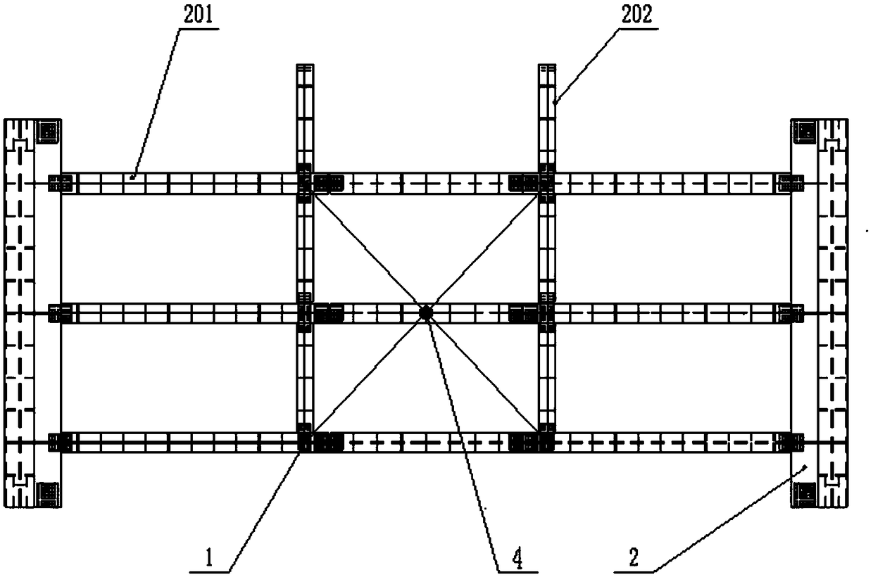
[0034] Step two, such as Image 6 As shown, select a plurality of positions for installing the assembled steel lifting lug device 1 on the beam or longitudinal beam of the steel truss beam unit 2, and fix the assembled steel lifting lug device 1 on the steel truss beam unit 2 through high-strength bolts 3 ;

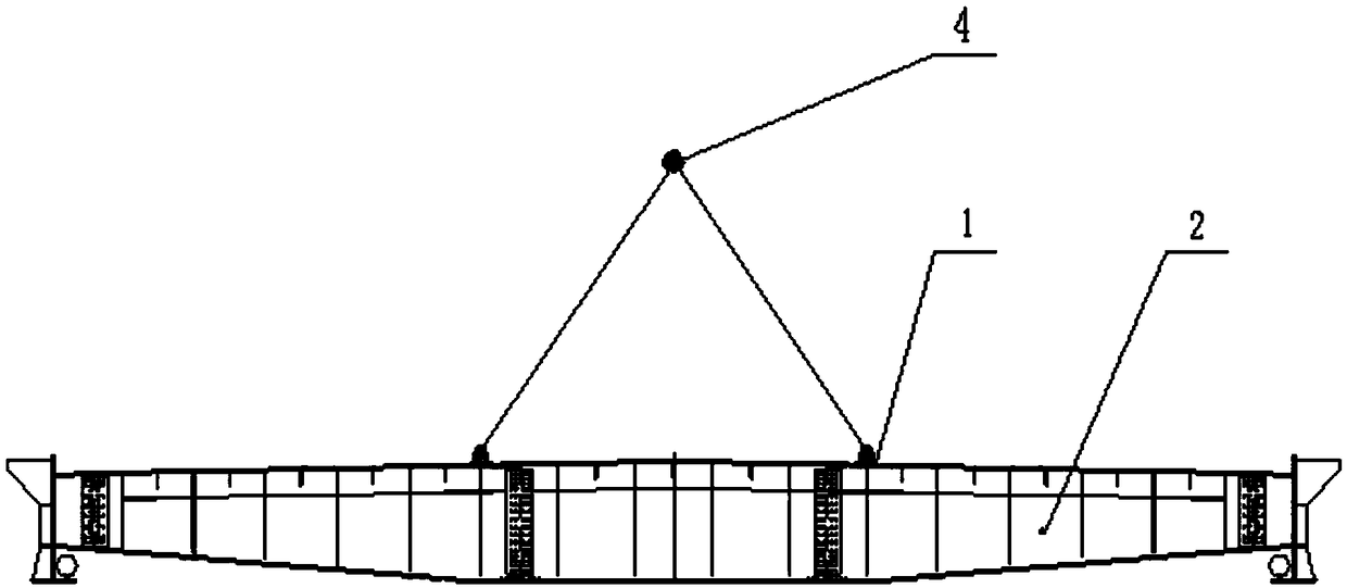
[0035] Step 3: Transport the lifting equipment to the top of the steel truss girder unit 2. The lifting equipment is connected to the assembled steel lifting lug device 1 through multiple lifting wire ropes, slings or hanging plates. The number of lug devices 1 is the same, and the location of the assembled steel lug device 1 is the lifting connection lifting point. When lifting, all the lifting connection lifting points converge to the single lift...

Embodiment 2

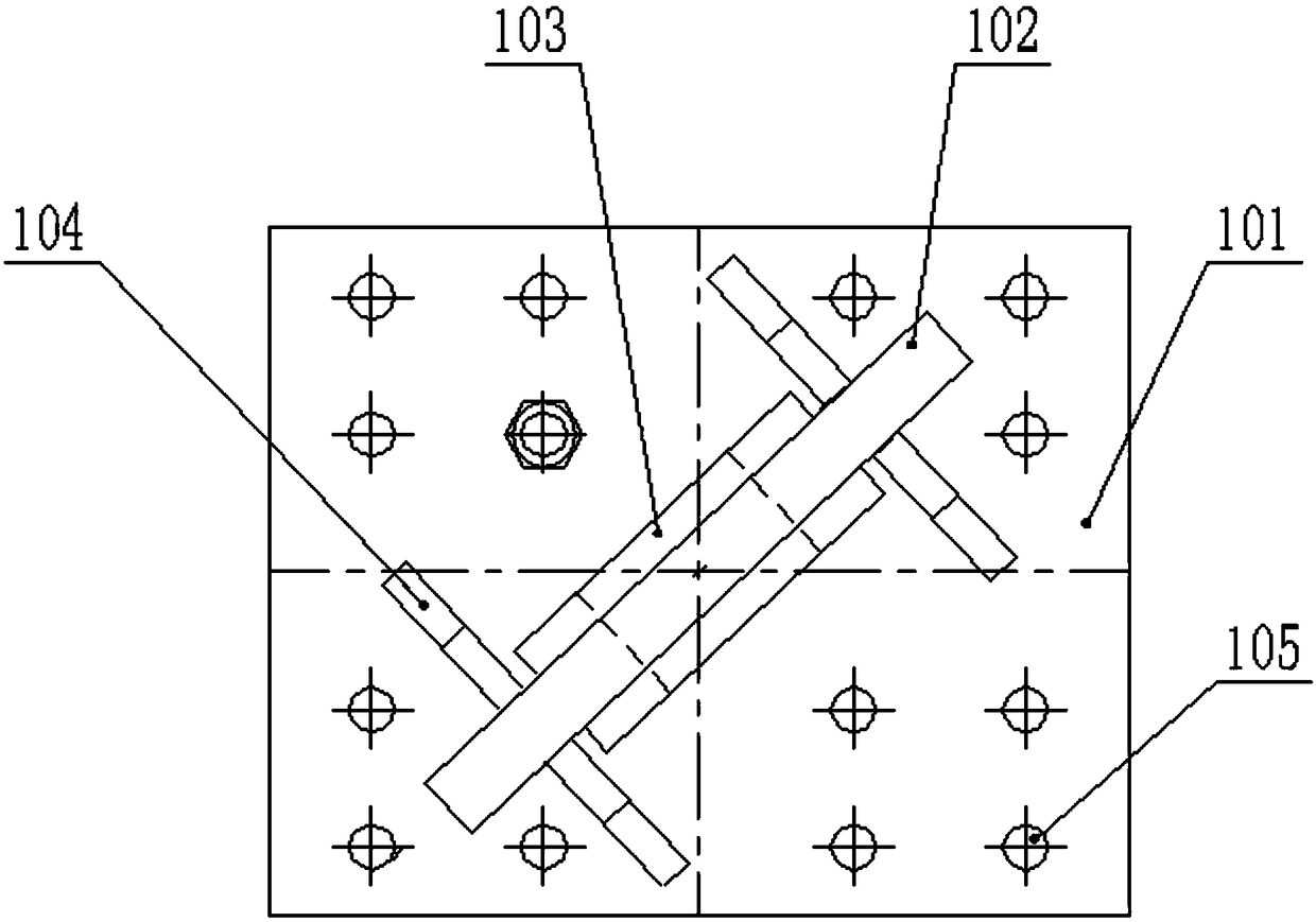
[0041] like image 3 , Figure 4 and Figure 5 As shown, on the basis of Example 1, the assembled steel lug device 1 is composed of a pressure-bearing connecting plate 101, an ear plate 102, a reinforcing plate 103 and a stiffening plate 104, and the pressure-bearing connecting plate 101 is rectangular As a steel plate member, the ear plate 102 is obliquely and vertically welded on the pressure-bearing connecting plate 101, and the center of the top of the ear plate 102 is provided with a hoisting hole. There are two reinforcing plates 103, and the two reinforcing plates 103 are respectively welded to the ear plate 102 and clamp the ear plate 102 in the middle, and the center of the reinforcing plate 103 is provided with a hoisting hole with the same specifications as the hoisting hole of the ear plate 102. There are several stiffening plates 104, and several stiffening plates The plates 104 are welded perpendicular to the ear plate 102 at the angle between the pressure-bear...

Embodiment 3

[0046] Preferably, the stiffening plate 104 is made of Q345 steel plate with a thickness of 12 mm. There are four stiffening plates 104 in total, and two of them form a group opposite to each other and are welded at the angle between the pressure-bearing connecting plate 101 and the lug plate 102 . Both the ear plate 102 and the reinforcing plate 103 are made of Q345 steel plate, the ear plate 102 is 30 mm thick, the reinforcing plate 103 is a circular steel plate with a diameter of φ220 mm and a thickness of 10 mm, and the ear plate 102 and the reinforcing plate 103 are hoisted through the same hole. The hole diameter is φ100mm. The size of the pressure-bearing connecting plate 101 is 500×400 mm, the thickness is 25 mm, and the material is a rectangular steel plate of Q345. There are several holes on the rectangular steel plate for connecting the pressure-bearing connecting plate 101 to the steel truss unit 2 Bolt holes 105.


PUM

PropertyMeasurementUnit
Thicknessaaaaaaaaaa
Diameteraaaaaaaaaa

Abstract

The invention provides a steel truss girder unit lifting method used in a lifting mode of a single lifting point. In lifting mounting construction of a steel truss girder, an assembling type steel lifting lug device is connected with a steel truss girder unit by using high-strength bolts, and is further connected with crane equipment through a lifting steel wire rope or a lifting belt, and then lifting connection of the steel truss girder unit is achieved. After bridging mounting construction of the steel truss girder unit, the high-strength bolts of steel lifting lugs and the steel truss girder unit are released, and the steel lifting lug device is disassembled and transferred to lifting construction of a next section of the steel truss girder. By adopting the lifting connection method, lifting connection design of the steel truss girder unit under a single lifting point condition is achieved, the steel truss girder unit is convenient and rapid to mount and dismount in the construction application process, can be transferred and reused, is safe, efficient, economic and practical, and the method is worthy of further popularization and application in later lifting connection designof similar steel truss girder units.

Description

technical field [0001] The invention belongs to the technical field of hoisting and construction of steel truss girders, and in particular relates to a hoisting method for steel truss girder units in a single hoisting point hoisting mode, especially for steel truss girder unit bridges of long-span steel structure cable-stayed bridges or suspension bridges Bit overall lifting installation construction. Background technique [0002] For the hoisting and installation design of the main girder bridge position of long-span steel structure cable-stayed bridges or suspension bridges, in the hoisting connection design of steel truss girder units under the single lifting point hoisting mode, direct welding on the rods of steel truss girder units is generally used Carry out by lifting the lug plate. The lifting connection method using welded lugs requires a corresponding number of lifting connection lugs to be installed on each steel truss girder. The material investment is large, th...

Claims


Application Information

Patent Timeline
IPC IPC(8): B66C1/12
CPCB66C1/12
Inventor 宁凯刘苗李维生涂哲贾红兵马建磊高权谢文轩李海瑞孔令洲徐克元苏广
Owner CCCC SHEC SECOND ENG
Why Eureka
Try Eureka