Method and system for multi-channel ink-jet printing

a multi-channel inkjet and printing method technology, applied in the direction of pattern printing, printing, duplicating/marking methods, etc., can solve the problems of distorting the image seen by the observer, interfering with the color of inks, and ink-jet printing techniques on non-white substrates

Inactive Publication Date: 2006-07-20
ELECTRONICS FOR IMAGING INC
View PDF12 Cites 126 Cited by
  • Summary
  • Abstract
  • Description
  • Claims
  • Application Information

AI Technical Summary

Benefits of technology

[0010] Similarly, in the multi-channel post-coat mode, the controller causes a first set of nozzles on the first group of printheads to deposit inks onto the substrate, and a second set of nozzles from the second group of printheads to deposit a coating fluid, such as white ink, onto the substrate. In this mode, however, the first set of nozzles depositing the inks are located adjacent to the leading edge of the substrate, and the second set of nozzles depositing the coating layer are adjacent to the trailing edge of the substrate, as the substrate advances under the print heads. Thus, each successive section of the substrate first receives an image layer from the first (leading) group of nozzles, and the coating layer is then applied over image by the second (trailing) group of nozzles. Accordingly, the printing system is able to simultaneously deposit both the image layer, and the post-coat layer, using a single printhead array arranged along a single axis, during a single printing operation.
[0012] The present invention is advantageous in that it allows for both pre-coating and post-coating operations using a conventional printhead arrangement, in which all of the printheads are aligned along a single axis. Thus, the carriage holding the printheads can be made smaller as compared to similar printing systems for providing pre-coat and post-coat operations. Moreover, because the specialized printhead for providing the pre-coat and post-coat layers is arranged in-line with the conventional image-printing heads, a single print head can be used to provide both pre-coat and post-coat printing operations, which was not possible with existing systems.

Problems solved by technology

Otherwise, colors from behind the ink pattern can interfere with the colors of the inks and distort the image seen by the observer.
One drawback to the existing techniques for ink-jet printing on non-white substrates is that they require a separate “pre-coating” or “post-coating” step.
These additional steps can be performed on a separate printing system configured to print a layer of solid white ink, but this is an extremely time-consuming and costly solution.
One disadvantage to this type of system is that the printhead carriage must be made larger to accommodate the dedicated pre-coat and post-coat printheads, which are located outside of the main axis of color ink printheads.
Also, these extra printheads are relatively expensive, and can add significant costs to the printing system.

Method used


Image

  • Method and system for multi-channel ink-jet printing
  • Method and system for multi-channel ink-jet printing
  • Method and system for multi-channel ink-jet printing

Examples


Embodiment Construction

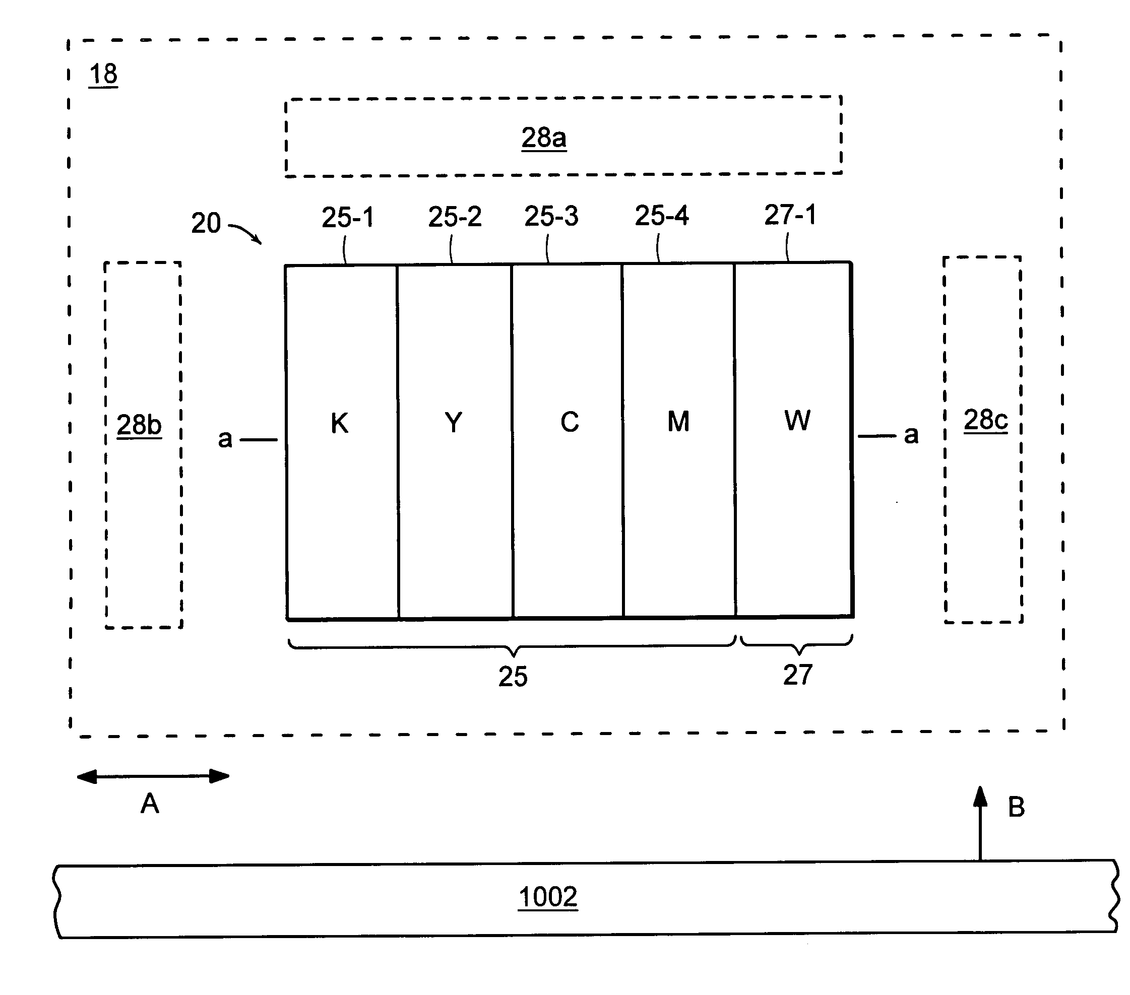
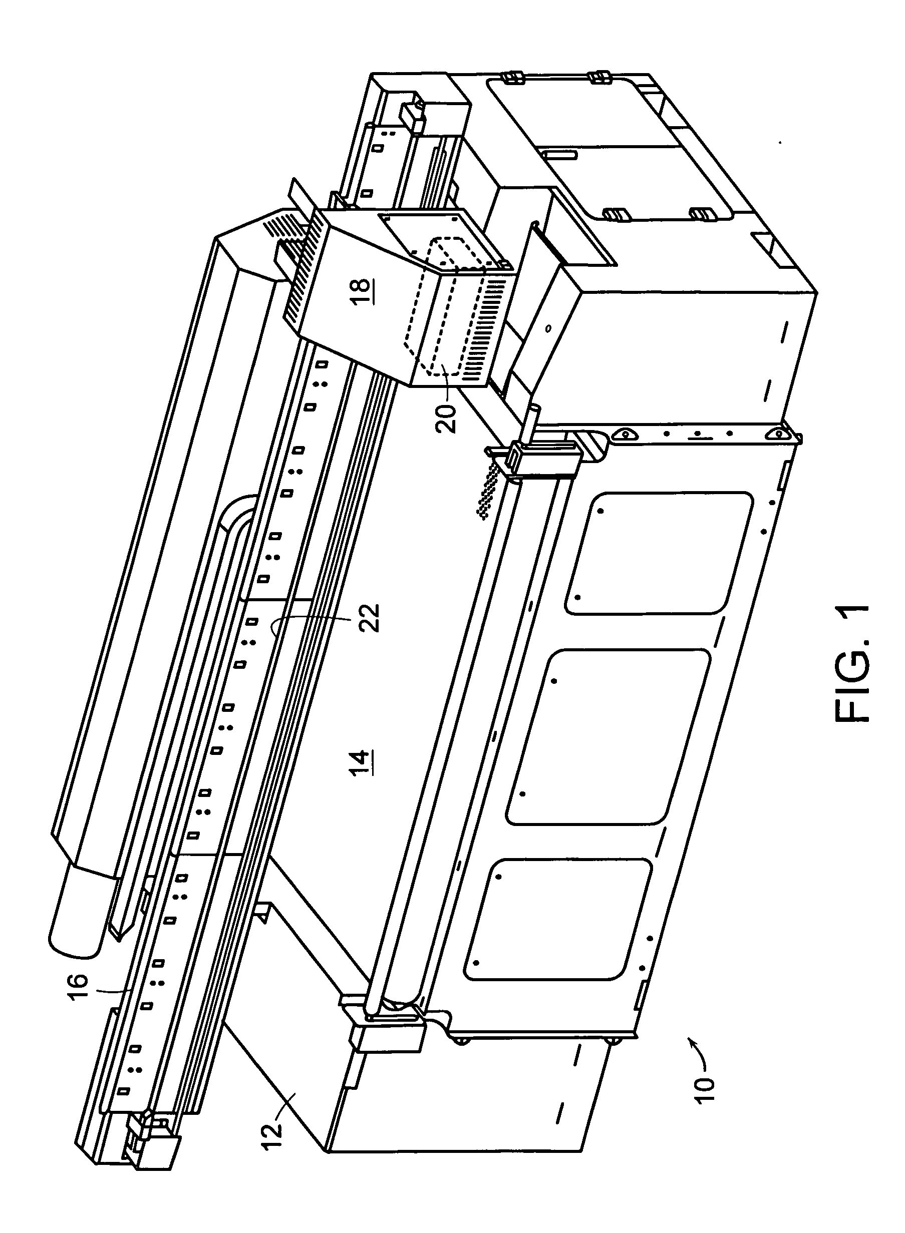
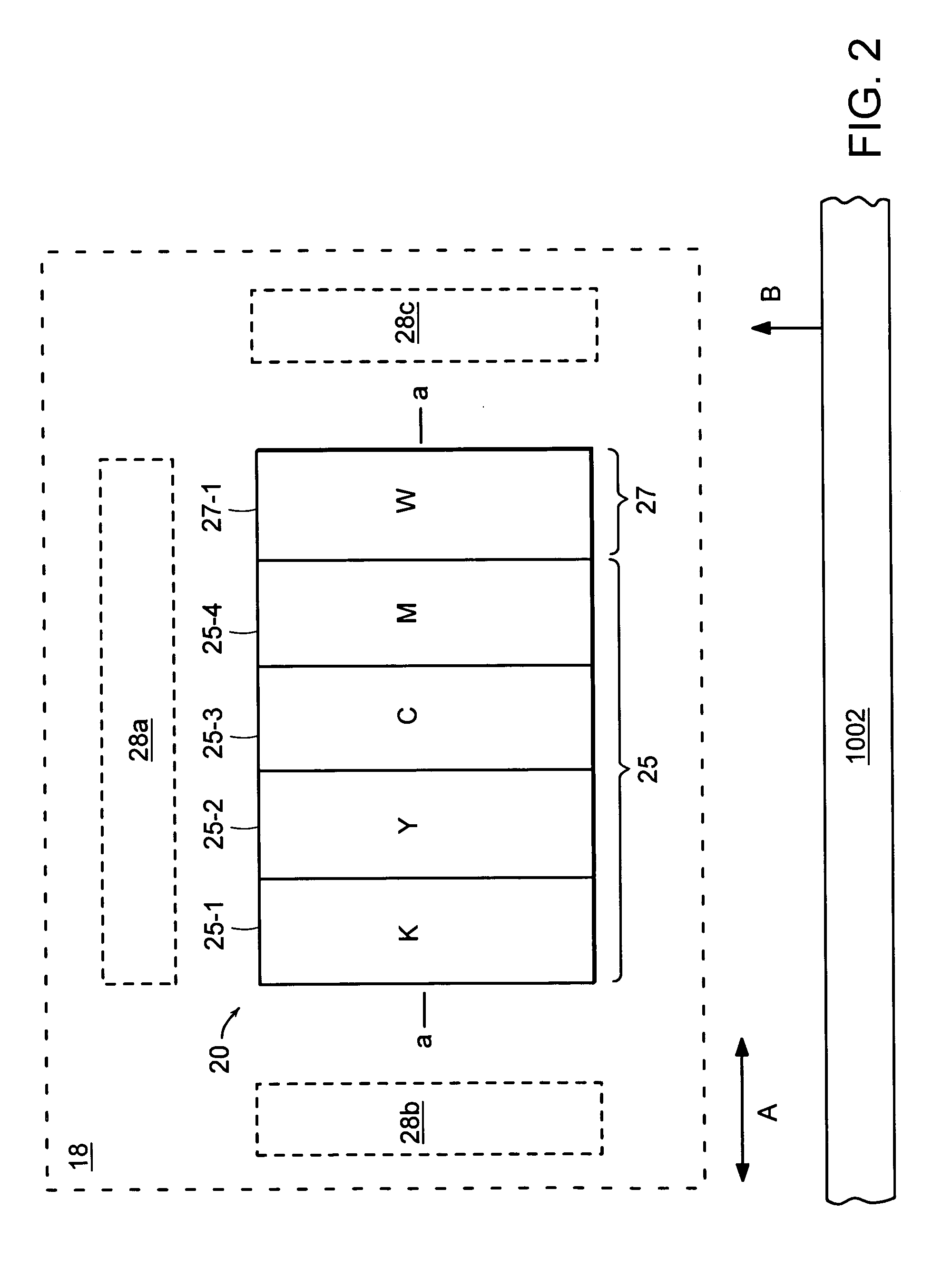
[0028] A description of preferred embodiments of the invention follows. Turning now to the drawings, there is shown in FIG. 1 a printing system 10 provided with a carriage 18. The carriage 18 holds a series of ink jet print heads 20 configured for printing images on a variety of substrates. Typical substrates are polyvinyl chloride (PVC) and reinforced vinyl. The printing system 10 is able to print on flexible as well as on non-flexible substrates, such as, for example, metals, glass, and plastics. The inks deposited can be solvent-based inks, or radiation (e.g. UV) curable inks used, for example, in printing systems described in U.S. Pat. No. 6,457,823 and U.S. application Ser. No. 10 / 172,761, filed Jun. 13, 2002, the entire teachings of which are incorporated herein by reference.

[0029] In addition to the carriage 18, the printing system 10 includes a base 12, a transport belt 14 which moves a substrate positioned on top of the belt 14 through the printing system 10, and a rail sy...


PUM

PropertyMeasurementUnit
transparentaaaaaaaaaa
colorsaaaaaaaaaa
pressureaaaaaaaaaa

Abstract

A printing apparatus having an array of printheads arranged along a single printhead axis, and capable of printing images and a coating layer on the substrate during a single printing operation. The coating layer can comprise a specialized printing fluid such as a layer of substantially white ink. The apparatus can perform a pre-coat printing operation, in which the coating layer is deposited first on the substrate, and the image is then printed over the coating layer. The apparatus can also perform a post-coat printing operation, in which the image is first printed onto the substrate, and the coating layer is then deposited over the image. The printhead array includes at least one printhead for printing inks to form the images, and at least one printhead for printing a specialized fluid to form the coating layer. Depending on the printing mode, a controller allocates certain nozzles of the array for printing inks and certain nozzles for printing the specialized fluid. As each section of a substrate advances under the array, it first receives a coating layer, and then an image layer; or it first receives an image layer and then a coating layer. The invention is particularly advantageous for printing on non-white and transparent substrates, as well as for printing backlit signs.

Description

BACKGROUND OF THE INVENTION [0001] Certain types of printing systems are adapted for printing images on large-scale printing media, such as for museum displays, billboards, sails, bus boards, and banners. Some of these systems use so-called drop on demand ink jet printing. In these systems, a piezoelectric vibrator applies pressure to an ink reservoir of the printhead to force the ink out through the nozzle orifices positioned on the underside of the printheads. A set of print heads are typically arranged in a row along a single axis within a printhead carriage. As the carriage scans back and forth along the direction of the printhead axis, the print heads deposit ink across the width of the substrate. A particular image is created by controlling the order at which ink is ejected from the various nozzle orifices.[0002] Some of these systems use inks with different colors to create the desired image. For instance, black, yellow, cyan, and magenta colored inks are commonly employed al...

Claims


Application Information

Patent Timeline
Patent Type & Authority Applications(United States)
IPC IPC(8): B41J2/21
CPCB41J2/2114B41J2/2117B41J11/0015B41M3/008B41M5/0047B41M5/0064B41M5/007B41M7/0036
Inventor SPEVAK, LARRY M.CURRIER, KEVIN C.SYVERSON, MICHAEL A.FRANCKE, GREGORY P.
Owner ELECTRONICS FOR IMAGING INC
Why Eureka
Try Eureka