Heat dissipation structure of intelligent power module, display module having the same, and method for installing heat dissipation plate for intelligent power module

a technology of intelligent power modules and heat dissipation structures, which is applied in the direction of electrical apparatus casings/cabinets/drawers, instruments, and semiconductor/solid-state device details, etc., can solve the problems of large amount of heat generated during operation and insufficient heat dissipation by itself to prevent the damage of circuit devices, etc., to achieve the effect of improving the heat dissipation structure of intelligent power modules

Inactive Publication Date: 2006-07-20
SAMSUNG SDI CO LTD
View PDF6 Cites 17 Cited by
  • Summary
  • Abstract
  • Description
  • Claims
  • Application Information

AI Technical Summary

Benefits of technology

[0009] It is therefore an object of the present invention to provide an improved heat dissipation structure for an intelligent power module.

Problems solved by technology

In the intelligent power module, a large amount of heat is generated during operation, especially when there are frequent switch operations and when transformations are performed.
However, the heat dissipater by itself is insufficient in preventing the circuit devices from being damaged by heat or from malfunctioning.

Method used


Image

  • Heat dissipation structure of intelligent power module, display module having the same, and method for installing heat dissipation plate for intelligent power module
  • Heat dissipation structure of intelligent power module, display module having the same, and method for installing heat dissipation plate for intelligent power module
  • Heat dissipation structure of intelligent power module, display module having the same, and method for installing heat dissipation plate for intelligent power module

Examples


first embodiment

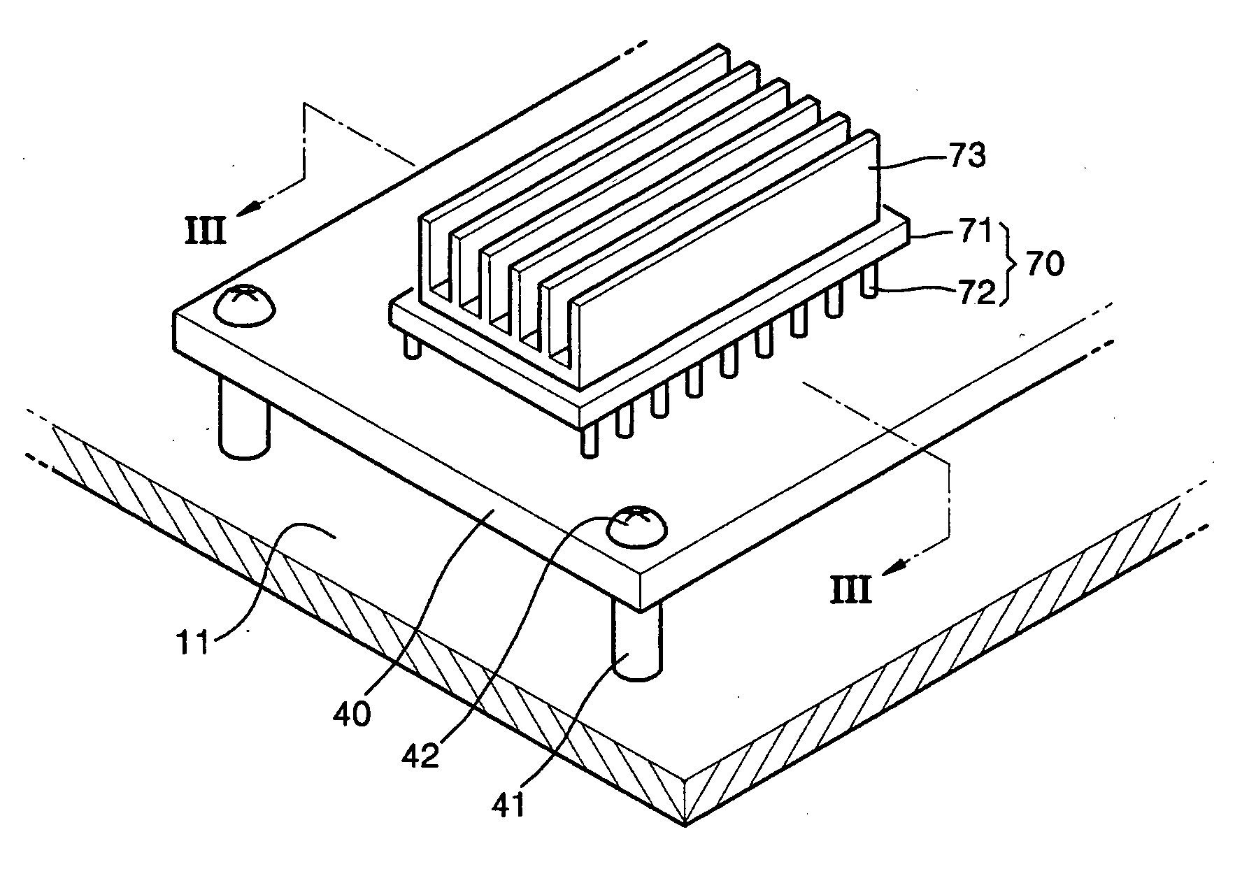
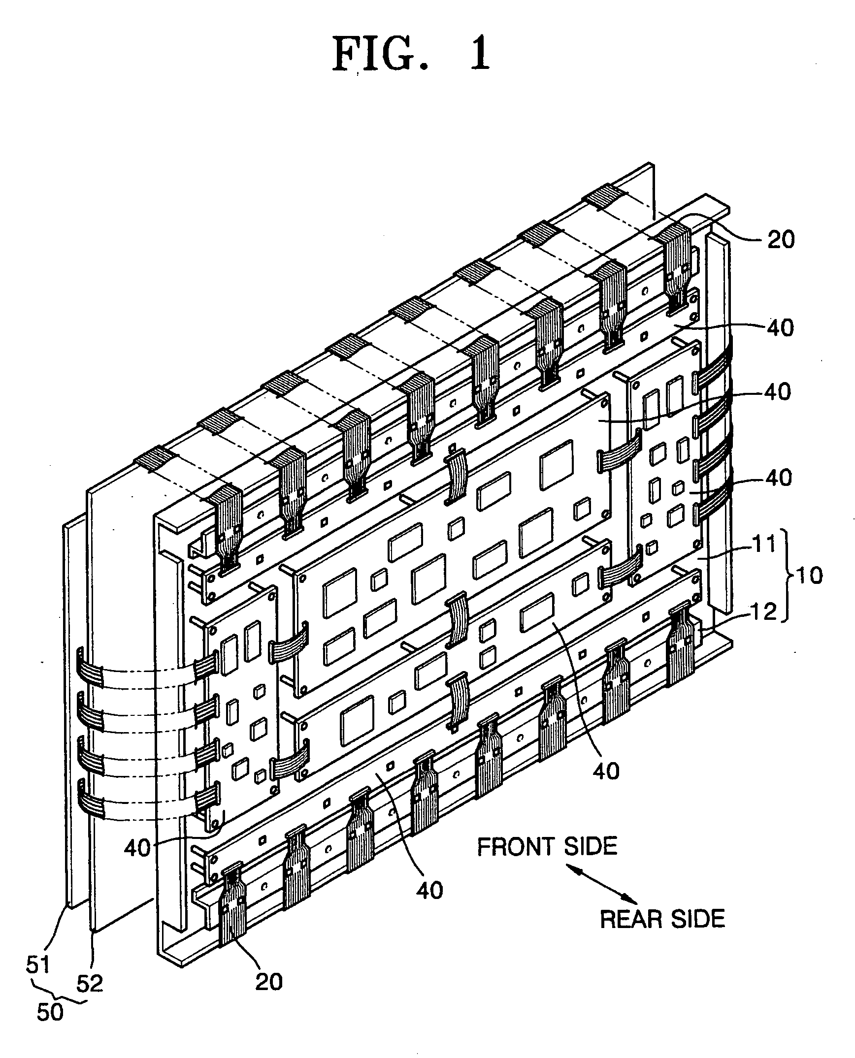
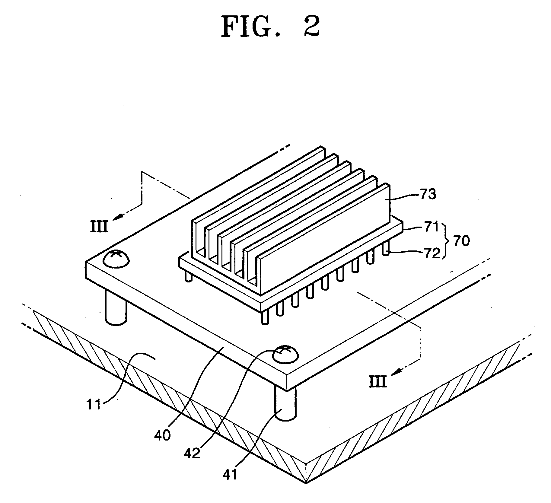
[0040] Turning now to FIG. 4, FIG. 4 is a cross-sectional view of a heat dissipation structure of an intelligent power module according to the present invention. Referring to FIG. 4, the heat dissipation structure of an intelligent power module includes the chassis base 11, an intelligent power module 70, a first heat dissipater 173, and a second heat dissipater 76. The circuit boards 40 can be typical printed circuit boards (PCBs). In the case of being applied to a display module as in the present invention, the circuit boards 40 are installed on a rear surface of the chassis base 11. When installed on the rear surface of the chassis base 11, the circuit boards 40 are coupled using a screw 42 to a boss (not illustrated) that is installed on the rear surface of the chassis base 11.

[0041] The intelligent power module 70 includes the circuit devices 74. The intelligent power module 70 is installed at one side of the drive circuit boards 40 using the connection pins 72. The circuit dev...

fourth embodiment

[0052] Turning now to FIG. 8, FIG. 8 is a cross-sectional view of the heat dissipation structure of an intelligent power module according to the present invention. Referring to FIG. 8, unlike the first three embodiments, a lower end of the second heat dissipater 276 is attached to the drive circuit boards 40 instead of the chassis base 11. An additional heat transfer unit (not shown), connecting the chassis base 11 and a portion of the drive circuit boards 40 where the second heat dissipater 276 is attached, can be further installed.

[0053] Drive circuit board 40 is a large non-metallic heat sink that are in constant contact with the atmosphere and has a much larger surface area in contact with the atmosphere than the first heat dissipater 173. As a result, second heat dissipater 276 serves to conduct heat to the large heat sink of the drive circuit boards 40 so that heat generated by the circuit devices 74 can be dissipated more effectively. The result is that the circuit devices 74...


PUM


Abstract

A heat dissipation structure of an intelligent power module includes a chassis base, a drive circuit board arranged on the chassis base, an intelligent power module arranged at a side of the drive circuit board, the intelligent power module comprising a plurality of circuit devices, a first heat dissipater having one surface contacting a surface of the intelligent power module, the first heat dissipater being adapted to dissipate heat generated by operation of the plurality of circuit devices, and a second heat dissipater having one side arranged in contact with another surface of the first heat dissipater and another side arranged to contact a surface of the chassis base.

Description

CLAIM OF PRIORITY [0001] This application makes reference to, incorporates the same herein, and claims all benefits accruing under 35 U.S.C.§ 119 from an application for HEAT DISSIPATION STRUCTURE OF INTELLIGENT POWER MODULE, DISPLAY MODULE HAVING THE SAME, AND METHOD FOR INSTALLING HEAT DISSIPATION PLATE FOR INTELLIGENT POWER MODULE earlier filed in the Korean Intellectual Property Office on 15 Jan. 2005 and there duly assigned Ser. No. 10-2005-0003980. BACKGROUND OF THE INVENTION [0002] 1. Field of the Invention [0003] A heat dissipation structure of an intelligent power module, a display module having the same, and a method for installing the heat dissipation structure, and more particularly, to a heat dissipation structure of an intelligent power module that has improved heat dissipation performance and is easy to install, a display module having the same, and a method for installing the heat dissipation structure for the intelligent power module. [0004] 2. Description of the Re...

Claims


Application Information

Patent Timeline
Patent Type & Authority Applications(United States)
IPC IPC(8): G06F1/20H01L23/36H01L23/40H05K7/20
CPCH05K7/20963H01L2924/0002H01L2924/00B62K21/16B62K21/22
Inventor JEONG, KWANG-JIN
Owner SAMSUNG SDI CO LTD
Why Eureka
Try Eureka