DC-DC converter of multi-output type

a converter and multi-output technology, applied in bridges, process and machine control, instruments, etc., can solve the problems of affecting the ideal cross-regulation of dc outputs, and affecting the effect of dc output voltage vsub>o1/sub>to rise,

Inactive Publication Date: 2006-07-20
SANKEN ELECTRIC CO LTD
View PDF11 Cites 44 Cited by
  • Summary
  • Abstract
  • Description
  • Claims
  • Application Information

AI Technical Summary

Benefits of technology

[0021] The moment first or second primary switching element (2, 3) is turned on or when a predetermined period of time elapses after first or second primary switching element (2, 3) is turned on, secondary switching element (20) is turned on to produce electric current flowing through second secondary winding (5c). When secondary switching element (20) is turned off under this condition, serge voltage occurs due to inductance of second secondary winding (5c), and associated serge voltage is induced on first secondary winding (5b). When first rectifying smoother (9) is connected to load under the light- or no-load condition, first output voltage (VO1) rises by the amount of serge voltage. In this case, first and second secondary windings (5b, 5c) of transformer (5) are in the electromagnetic sparse coupling which can reduce, attenuate or relax serge voltage induced on first secondary winding (5b). This restrains or controls potential increase in first output voltage (VO1) resulted from serge voltage through first rectifying smoother (9) under the light- or no-load condition to control fluctuation in second output voltage (VO2) through second rectifying smoother (17) without restricting transmission of electric power from the primary to the secondary side making use of feedback control to primary control circuit (14) although serge voltage appears under the light- or no-load condition. Accordingly, the converter according to the present invention can generate stable first and second DC output voltages (VO2, VO2) throughout the entire loaded and unloaded range.

Problems solved by technology

Specifically, with higher output voltage VO1, error signal VE1 has the higher voltage level to reduce the operating frequency, thereby causing output voltage VO1 to fall down, adversely, with lower output voltage VO1, error signal VE1 has the lower voltage level to increase the operating frequency, thereby causing the output voltage VO1 to rise.
Also, as magnitude of surge voltage is proportional to ramp of ripple current, inclination of winding current becomes greater when larger ripple current occurs, thereby causing possible larger surge voltage and considerable voltage fluctuation to appear on first secondary winding.
In this way, the prior art converter is disadvantageous in that second DC output voltage VO2 is inconveniently made step-down or fluctuant upon occurrence of serge voltage under the light- or no-load condition, and this unstable output voltage obviously impedes ideal cross-regulation to all DC outputs.

Method used


Image

  • DC-DC converter of multi-output type
  • DC-DC converter of multi-output type
  • DC-DC converter of multi-output type

Examples


first embodiment

[0035]FIG. 8 is a cross-sectional view of a transformer which is substituted for the prior art transformer shown in FIG. 2 to form the DC-DC converter of multi-output type according to the present invention in the converter circuit shown in FIG. 1. The transformer 5 shown in FIG. 8 includes second secondary winding 5c, primary winding 5a and first secondary winding 5b concentrically wound in the outward order around a cylindrical portion 5m between a pair of flanges 5n and 5o of a bobbin 5l in a layered structure, and cylindrical insulating papers 5q are also coaxially interposed between second secondary winding 5c and primary winding 5a and between primary winding 5a and first secondary winding 5b. Columnar intermediate legs 5k formed with E-shaped core halves 5g and 5h are positioned in cylindrical portion 5m of bobbin 5l. This arrangement can attain the reduction in the magnetic flux interlinkage number between first and second secondary windings 5b and 5c to accomplish the mutua...

second embodiment

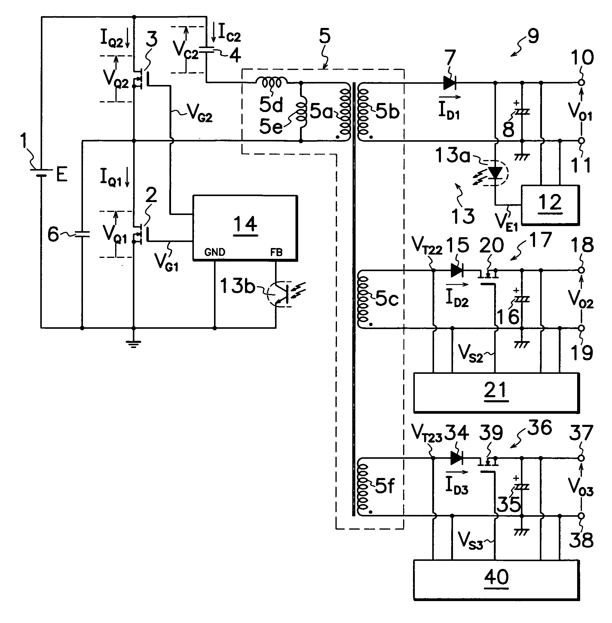
[0037] DC-DC converter shown in FIG. 1 may be modified to perform other different embodiments of the present invention. For example, FIG. 9 discloses the invention which additionally comprises a third secondary winding 5f in transformer 5; a third rectifying smoother 36 which includes a third output rectifying diode 34 and a third output smoothing capacitor 35 connected to third secondary winding 5f; an additional output control MOS-FET 39 connected between a cathode of third output rectifying diode 34 and third output smoothing capacitor 35; and an additional secondary control circuit 40 connected to third DC output terminals 37 and 38 and additional output control MOS-FET 39 for controlling the on-off operation of additional output control MOS-FET 39 based on the level of a third output voltage VO3 applied on third output smoothing capacitor 35. Other parts and construction in FIG. 9 are substantially similar to those in FIG. 1, and basic circuitry and its operation of the DC-DC c...

third embodiment

[0040]FIG. 11 illustrates a transformer 5 used for a third embodiment according to the present invention which comprises a first secondary winding 5b wound around cylindrical portion 5m of bobbin 5l between a pair of flanges 5n and 5o, a primary winding 5a wound over first secondary winding 5b through a first interlayer tape 5q, a second secondary winding 5c wound over primary winding 5a through a second interlayer tape 5q, a third secondary winding of wound over second secondary winding 5c, and a pair of E-shaped core halves 5g and 5h whose intermediate legs 5k are positioned in an inner chamber of cylindrical portion 5m of bobbin 5l. Thus, mediately wound around intermediate legs 5k between first and second, third secondary windings 5b and 5c, 5f is primary winding 5a which diminishes the magnetic flux interlinkage number between first and second secondary windings 5b and 5c and between first and third secondary windings 5b and 5f to thereby accomplish the mutual electromagnetic s...


PUM


Abstract

A DC-DC converter of multi-output type is provided wherein a primary winding 5a is wound around core halves 5g, 5h of a transformer 5 between first and second secondary windings 5b, 5c of transformer 5 also concentrically wound around core halves 5g, 5h to form an electromagnetic sparse coupling between first and second secondary windings 5b, 5c. When on-off operation of first and second primary MOS-FETs 2, 3 generates first and second DC outputs VO1, VO2, the electromagnetic sparse coupling can reduce, attenuate or relax serge voltage induced on first secondary winding 5b. This restrains or controls potential increase in first output voltage VO1 resulted from serge voltage through first rectifying smoother 9 under the light- or no-load condition to control fluctuation in second output voltage VO2 through second rectifying smoother 17 without restricting transmission of electric power from the primary to the secondary side making use of feedback control to primary control circuit 14 in order to generate stable first and second DC output voltages VO1 and VO2 throughout the entire loaded and unloaded range.

Description

TECHNICAL FIELD [0001] This invention relates to a DC-DC converter of multi-output type capable of producing a plurality of outputs, in particular, stable outputs throughout the entire loaded and unloaded range. BACKGROUND OF THE INVENTION [0002] A DC-DC converter of multi-output type comprises a switching element and a resonance circuit provided on a primary side of a transformer to turn on and off the switching element in order to produce a plurality of outputs from a plurality of secondary windings of transformer through rectifying smoothers. Such DC-DC converters have been widely applied to inexpensive power sources for information processing appliances such as personal computers, and household electric appliances such as air-conditioners or audio or visual equipments. [0003] For example, a prior art DC-DC converter of multi-output type shown in FIG. 1 comprises first and second primary MOS-FETs 2 and 3 as first and second primary switching elements connected in series to a DC p...

Claims


Application Information

Patent Timeline
Patent Type & Authority Applications(United States)
IPC IPC(8): H02J1/00H02M3/00
CPCH02M3/33561H02M2001/008H02M1/008E01D4/00E01D19/00E01D2101/30
Inventor USUI, HIROSHI
Owner SANKEN ELECTRIC CO LTD
Why Eureka
Try Eureka