DC-DC converter of multi-output type
a converter and multi-output technology, applied in bridges, process and machine control, instruments, etc., can solve the problems of affecting the ideal cross-regulation of dc outputs, and affecting the effect of dc output voltage vsub>o1/sub>to rise,
- Summary
- Abstract
- Description
- Claims
- Application Information
AI Technical Summary
Benefits of technology
Problems solved by technology
Method used
Image
Examples
first embodiment
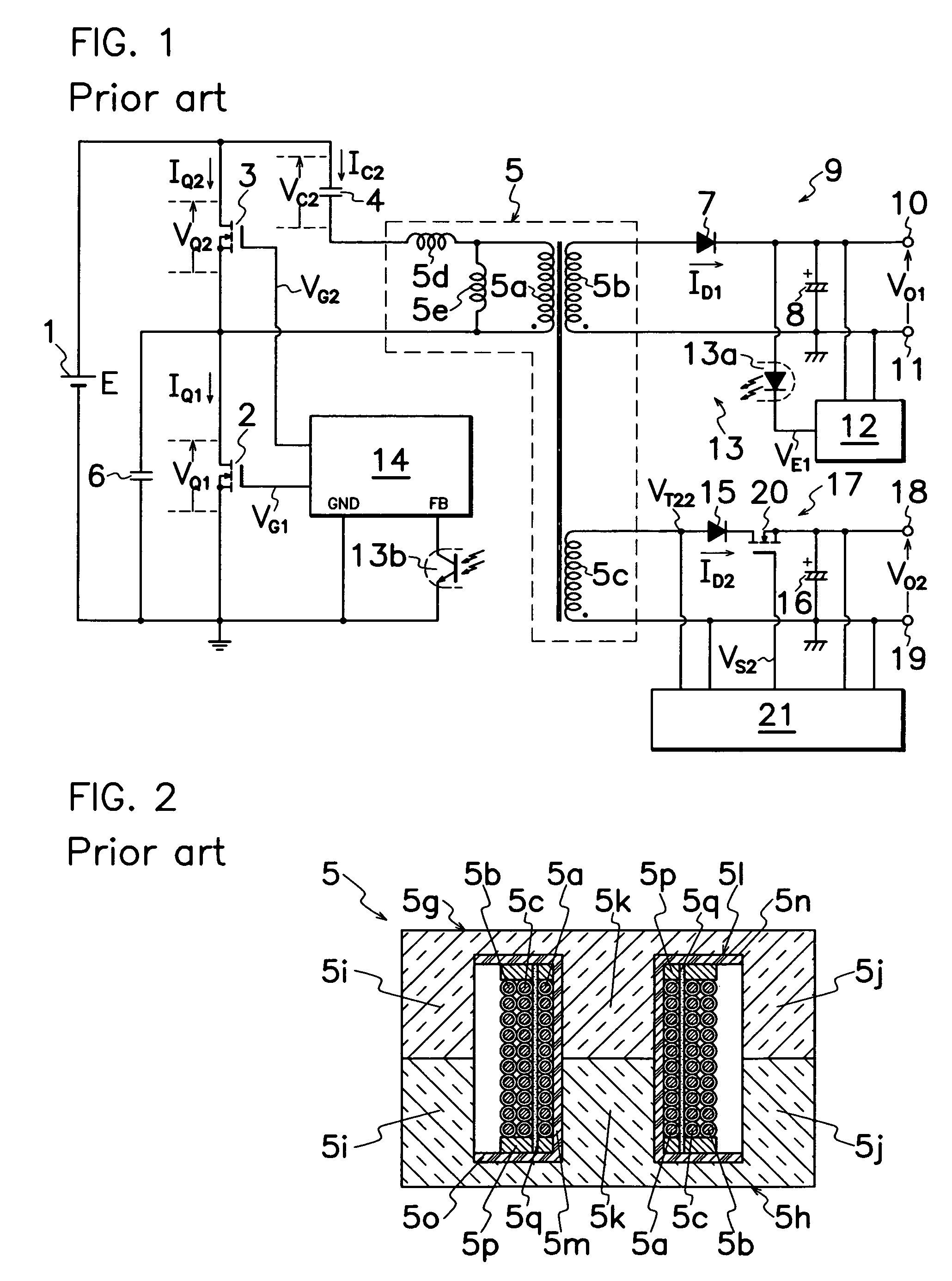
[0035]FIG. 8 is a cross-sectional view of a transformer which is substituted for the prior art transformer shown in FIG. 2 to form the DC-DC converter of multi-output type according to the present invention in the converter circuit shown in FIG. 1. The transformer 5 shown in FIG. 8 includes second secondary winding 5c, primary winding 5a and first secondary winding 5b concentrically wound in the outward order around a cylindrical portion 5m between a pair of flanges 5n and 5o of a bobbin 5l in a layered structure, and cylindrical insulating papers 5q are also coaxially interposed between second secondary winding 5c and primary winding 5a and between primary winding 5a and first secondary winding 5b. Columnar intermediate legs 5k formed with E-shaped core halves 5g and 5h are positioned in cylindrical portion 5m of bobbin 5l. This arrangement can attain the reduction in the magnetic flux interlinkage number between first and second secondary windings 5b and 5c to accomplish the mutua...
second embodiment
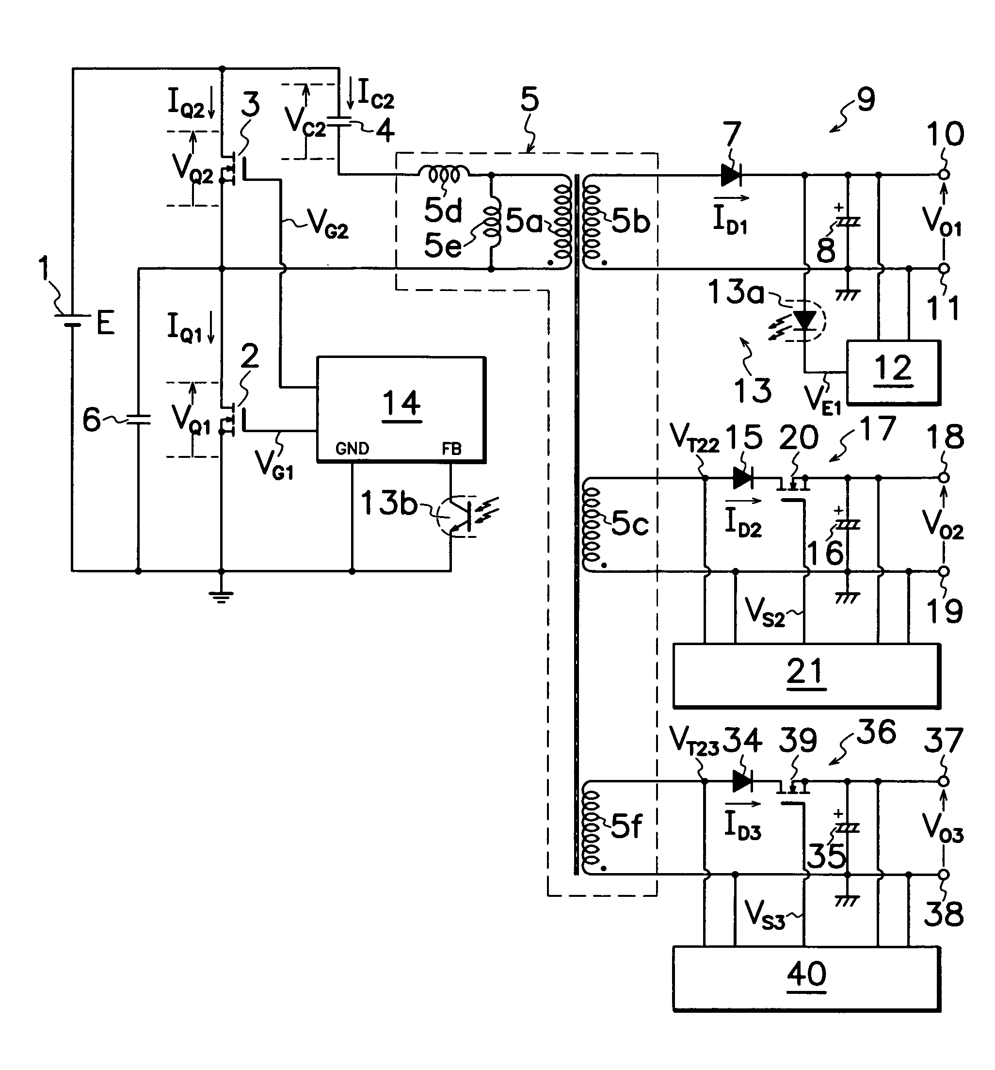
[0037]DC-DC converter shown in FIG. 1 may be modified to perform other different embodiments of the present invention. For example, FIG. 9 discloses the invention which additionally comprises a third secondary winding 5f in transformer 5; a third rectifying smoother 36 which includes a third output rectifying diode 34 and a third output smoothing capacitor 35 connected to third secondary winding 5f; an additional output control MOS-FET 39 connected between a cathode of third output rectifying diode 34 and third output smoothing capacitor 35; and an additional secondary control circuit 40 connected to third DC output terminals 37 and 38 and additional output control MOS-FET 39 for controlling the on-off operation of additional output control MOS-FET 39 based on the level of a third output voltage VO3 applied on third output smoothing capacitor 35. Other parts and construction in FIG. 9 are substantially similar to those in FIG. 1, and basic circuitry and its operation of the DC-DC co...
third embodiment
[0040]FIG. 11 illustrates a transformer 5 used for a third embodiment according to the present invention which comprises a first secondary winding 5b wound around cylindrical portion 5m of bobbin 5l between a pair of flanges 5n and 5o, a primary winding 5a wound over first secondary winding 5b through a first interlayer tape 5q, a second secondary winding 5c wound over primary winding 5a through a second interlayer tape 5q, a third secondary winding of wound over second secondary winding 5c, and a pair of E-shaped core halves 5g and 5h whose intermediate legs 5k are positioned in an inner chamber of cylindrical portion 5m of bobbin 5l. Thus, mediately wound around intermediate legs 5k between first and second, third secondary windings 5b and 5c, 5f is primary winding 5a which diminishes the magnetic flux interlinkage number between first and second secondary windings 5b and 5c and between first and third secondary windings 5b and 5f to thereby accomplish the mutual electromagnetic s...
PUM
| Property | Measurement | Unit |
|---|---|---|
| output voltage | aaaaa | aaaaa |
| time | aaaaa | aaaaa |
| frequency | aaaaa | aaaaa |
Abstract
Description
Claims
Application Information
 - R&D
- Intellectual Property
- Life Sciences
- Materials
- Tech Scout
- Unparalleled Data Quality
- Higher Quality Content
- 60% Fewer Hallucinations
Browse by: Latest US Patents, China's latest patents, Technical Efficacy Thesaurus, Application Domain, Technology Topic, Popular Technical Reports.
© 2025 PatSnap. All rights reserved.Legal|Privacy policy|Modern Slavery Act Transparency Statement|Sitemap|About US| Contact US: help@patsnap.com


