Method and communication system employing secure key exchange for encoding and decoding messages between nodes of a communication network

Inactive Publication Date: 2006-07-20
EATON CORP
View PDF4 Cites 89 Cited by
  • Summary
  • Abstract
  • Description
  • Claims
  • Application Information

AI Technical Summary

Benefits of technology

[0024] These needs and others are met by the present invention, which provides a method to solve the problem of secure encryption key exchange with minimal user intervention and which provides a simple method to generate such encryption key based upon a mating time, which is known only to a pair of nodes

Problems solved by technology

A simple key exchange often proves to be a dominant obstacle in security implementation for wireless sensor networks.
This issue is magnified by the fact that low-cost embedded nodes of such wireless sensor networks are limited in resources.
However, the reuse of mechanisms applied in conventional computer networks to wireless sensor networks is not believed to be feasible due to the relatively extreme limita

Method used


Image

  • Method and communication system employing secure key exchange for encoding and decoding messages between nodes of a communication network
  • Method and communication system employing secure key exchange for encoding and decoding messages between nodes of a communication network
  • Method and communication system employing secure key exchange for encoding and decoding messages between nodes of a communication network

Examples


example 1

[0074]FIG. 4A shows an example of another fob 51, which may be the same as or similar to the fob 6 of FIG. 2, and a wireless system component 52 (e.g., a sensor 8,10; a base station 4; a device 12; a repeater 13), which are suitably mated for configuration of the system component 52 and / or the fob 51. The fob 51 includes a training / mating switch 54. The component 52 includes a surface or protrusion 56, which is designed to engage the switch 54. The component 52 also includes a training / mating switch 58 having an actuator 59. The fob 51 includes a protrusion or surface 60, which is designed to engage the switch actuator 59. Initially, the fob 51 is slid into the component 52. For example, the fob 51 includes an engagement portion (not shown) having a tongue (not shown), while the component 52 has a corresponding mating engagement recess (not shown) with a corresponding groove (not shown). As the component protrusion 56 approaches the fob switch 54, it engages and activates an actuato...

example 2

[0075]FIG. 4B shows an example of the sensor / base / device program switch 64 of a fob 66, and the sensor program switch 68 of a sensor 70. The fob 66 includes a case or enclosure 72 having an opening 74, a protrusion 76 and a printed circuit board 78 therein. The sensor / base / device program switch 64 is proximate the opening 74, and the sensor program switch 68 is on a printed circuit board 80 and proximate the opening 82 of the sensor case or enclosure 84. Whenever the fob 66 is suitably mated with the sensor 70, the fob protrusion 76 passes through the sensor opening 82 and engages the sensor program switch 68. At the same time, whenever the sensor 70 is suitably mated with the fob 66, the sensor protrusion 86 passes through the fob opening 74 and engages the sensor / base / device program switch 64.

example 3

[0076] As an alternative to the switches 64,68 and protrusions 76,86 of FIG. 4B, suitable proximity sensors (PS) 88,90 and targets (T) 92,94 may be employed as shown with the two nodes 96,98 of FIG. 4C. For example, the proximity sensors 88,90 are activated and deactivated whenever the node 96 is respectively suitably proximate to and distal from the node 98.

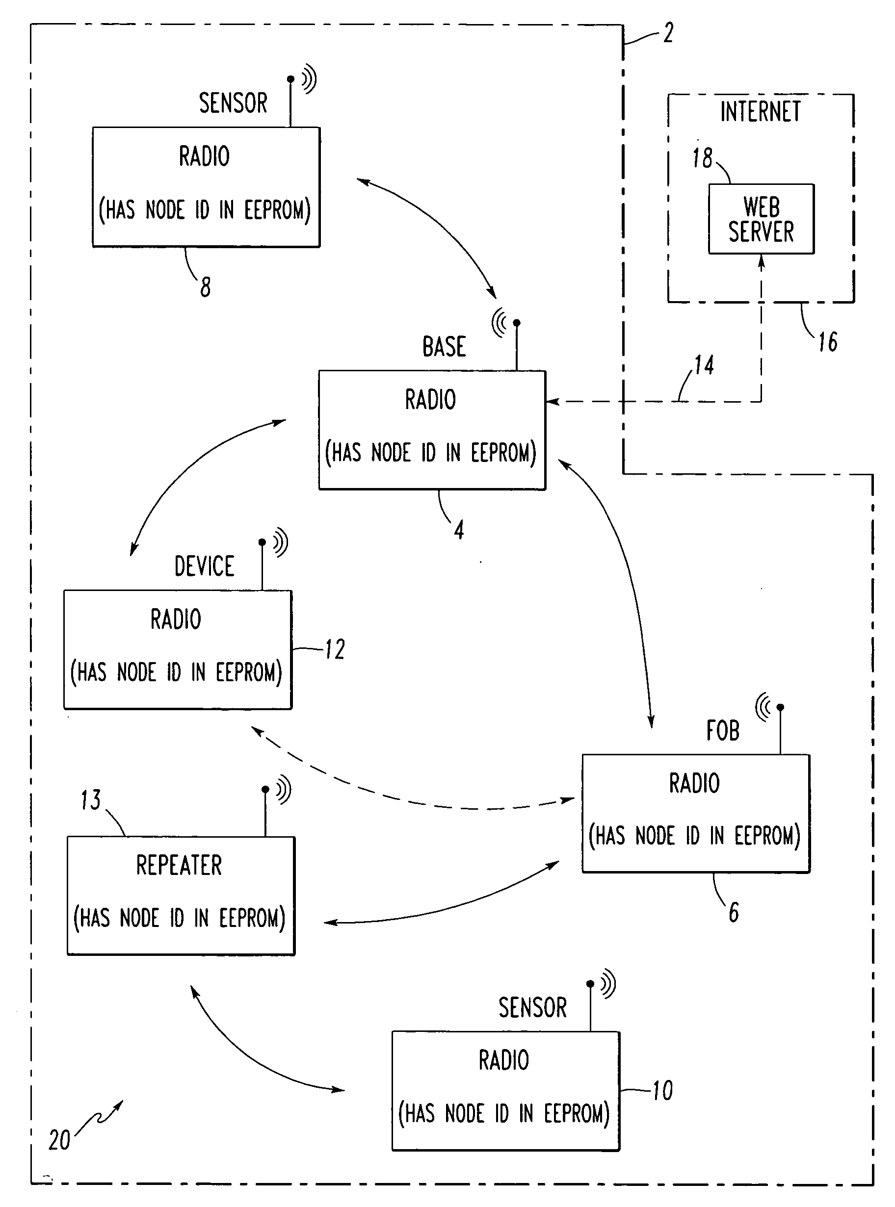
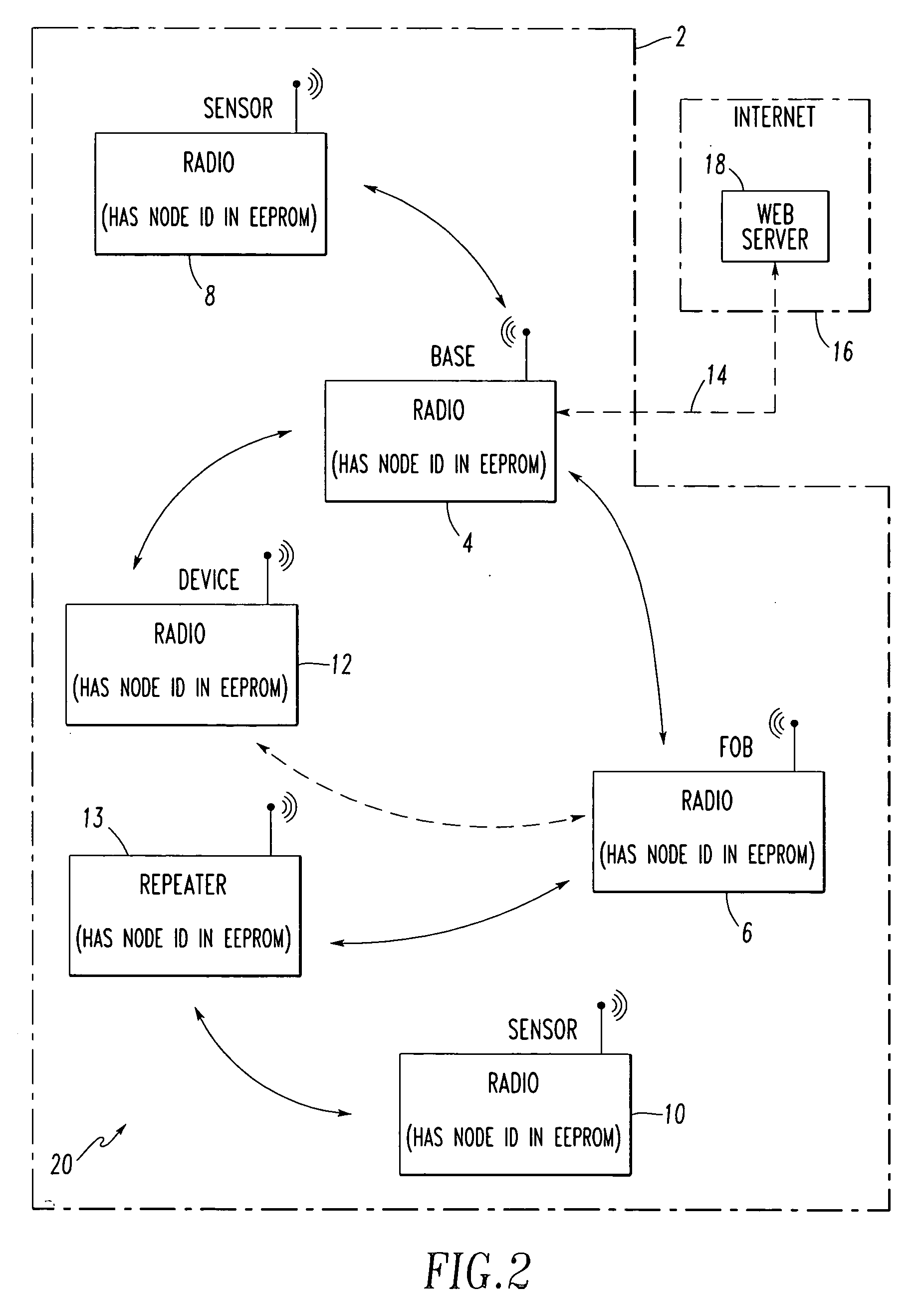
[0077]FIG. 5 shows an example sequence of events 100 employed to encode and decode messages between nodes, such as, for example, the fob 6 and the base station 4 of the communication network 20 of FIG. 2. First, at 102, a first node, such as the fob 6, is mated with a second node, such as the base station 4. Then, at 104, a time duration of the mating is determined in the first node and, at 106, the (same) time duration of the mating is determined in the second node. Next, at 108, an encryption key is generated based upon the time duration in the first node. Then, at 110, the (same) encryption key is generated based upon the (s...


PUM


Abstract

A method encodes and decodes messages between nodes of a wireless communication network. A first node, such as a fob, is mated with a second node, such as a base station, of the wireless communication network. A time duration of the mating is determined in the fob. The time duration of the mating is also determined in the base station. An encryption key is generated based upon the time duration in the fob. The encryption key is also generated based upon the time duration in the base station. Subsequently, communication messages over the wireless communication network are encrypted and decrypted between the fob and the base station employing the encryption key.

Description

BACKGROUND OF THE INVENTION [0001] 1. Field of the Invention [0002] This invention pertains generally to communication systems and, more particularly, to communication systems including communicating nodes, which encode and decode communication messages therebetween. The invention also pertains to a method for encoding and decoding communication messages between nodes of a communication network. [0003] 2. Background Information [0004] A simple key exchange often proves to be a dominant obstacle in security implementation for wireless sensor networks. This issue is magnified by the fact that low-cost embedded nodes of such wireless sensor networks are limited in resources. [0005] The problem of key exchange has been addressed efficiently in conventional computer networks. However, the reuse of mechanisms applied in conventional computer networks to wireless sensor networks is not believed to be feasible due to the relatively extreme limitations in resources available for computation ...

Claims


Application Information

Patent Timeline
IPC IPC(8): H04L9/00
CPCH04W12/04H04W84/18H04L9/0838H04L9/0872H04L2209/805H04W12/61H04W12/50
Inventor PEREIRA, LUIS R.SRINIVASAN, KAMALAVASAN
Owner EATON CORP
Why Eureka
Try Eureka