
System and method for analyzing video from non-static camera

a non-static camera and video analysis technology, applied in the field of surveillance systems and methods, can solve the problems of high resolution cameras, many cameras, and insufficient resolution of camera devices to acquire sufficient resolution images for some tasks,

Inactive Publication Date: 2006-07-20
IBM CORP
View PDF11 Cites 32 Cited by
  • Summary
  • Abstract
  • Description
  • Claims
  • Application Information

AI Technical Summary

Benefits of technology

[0010] It is a further object of the present invention to provide a system and method that generates “static” video streams from the video taken from a moving camera tour that permits the application of conventional “static camera” algorithms to be applied to moving cameras that cover a wide area.
[0016] Advantageously, the system and method for automatically understanding content (e.g., moving objects) in a video allowing for the application of conventional “static camera” algorithms permits the 24-hour vigilance of computer surveillance technology to be applied to moving (non-static) cameras that cover a wide area.

Problems solved by technology

It is expected that for some time to come, camera devices will not be of sufficiently high resolution to acquire sufficient resolution images for some tasks, e.g., surveillance, over wide fields of view.
High resolution cameras are expensive, and to cover wide areas they need special lenses that distort the images.
The alternative for complete coverage is using many cameras, which is also expensive.
Touring cameras allow coverage of a wide area with the penalty of not observing the whole area all the time.
However, the operator may choose a particular area of interest and steer the camera, which is very labour intensive and prone to error, i.e., it is easy to miss important information, which may have dire consequences for critical surveillance operations.
Processing video from a moving camera, such as a pan-tilt-zoom camera, is much more complex as methods such as background subtraction, that form the basis of most current analytics systems, need static cameras.
While known solutions implement optical flow analysis techniques for explicit detection of objects in moving cameras, these are less sensitive than static camera techniques, and moreover are computationally expensive.

Method used


Image

  • System and method for analyzing video from non-static camera
  • System and method for analyzing video from non-static camera
  • System and method for analyzing video from non-static camera

Examples


Embodiment Construction

[0021] The present invention is directed to a system and method for analyzing non-static camera images by spatio-temporally relating the (known) position of the camera and the corresponding images.

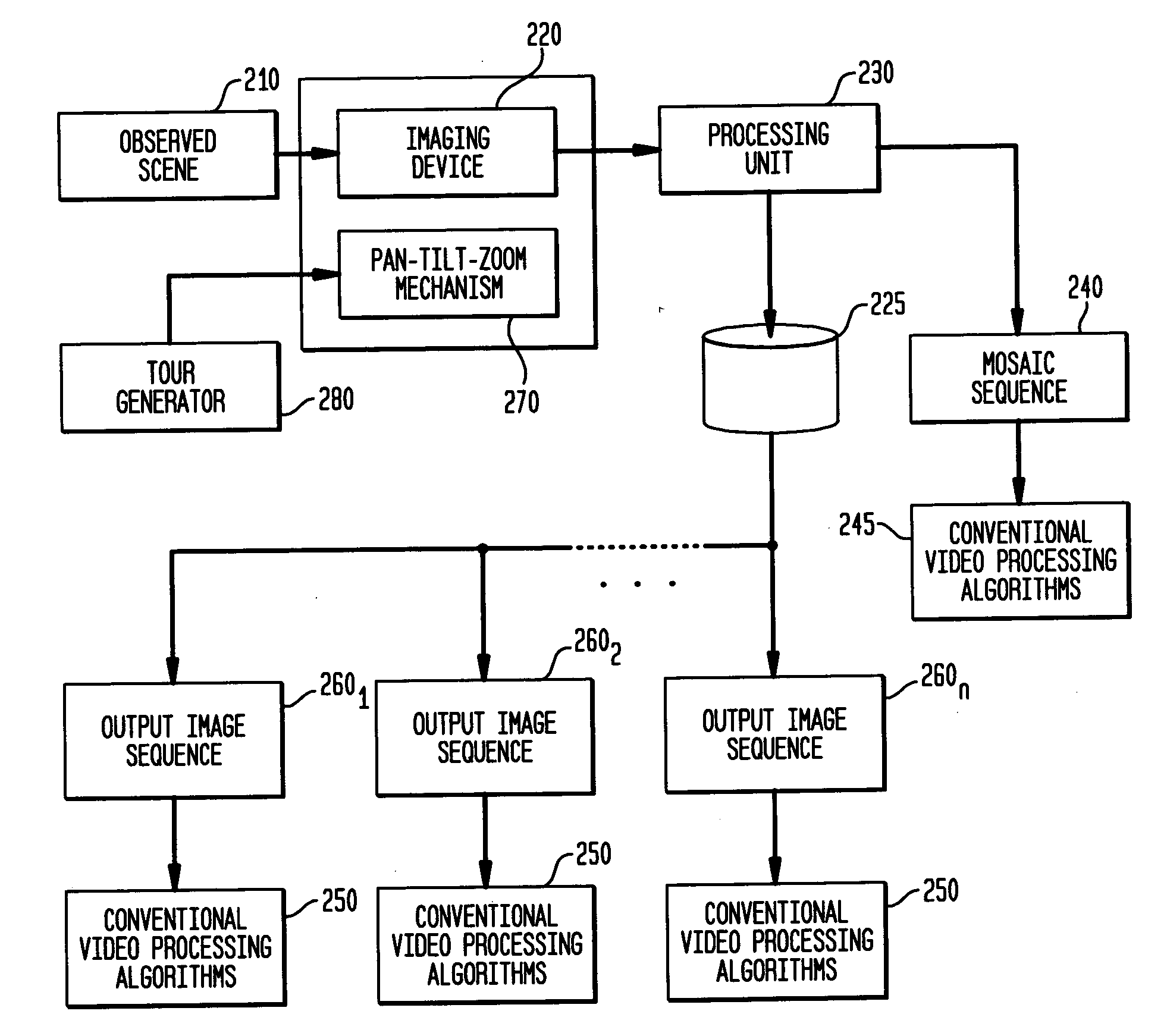
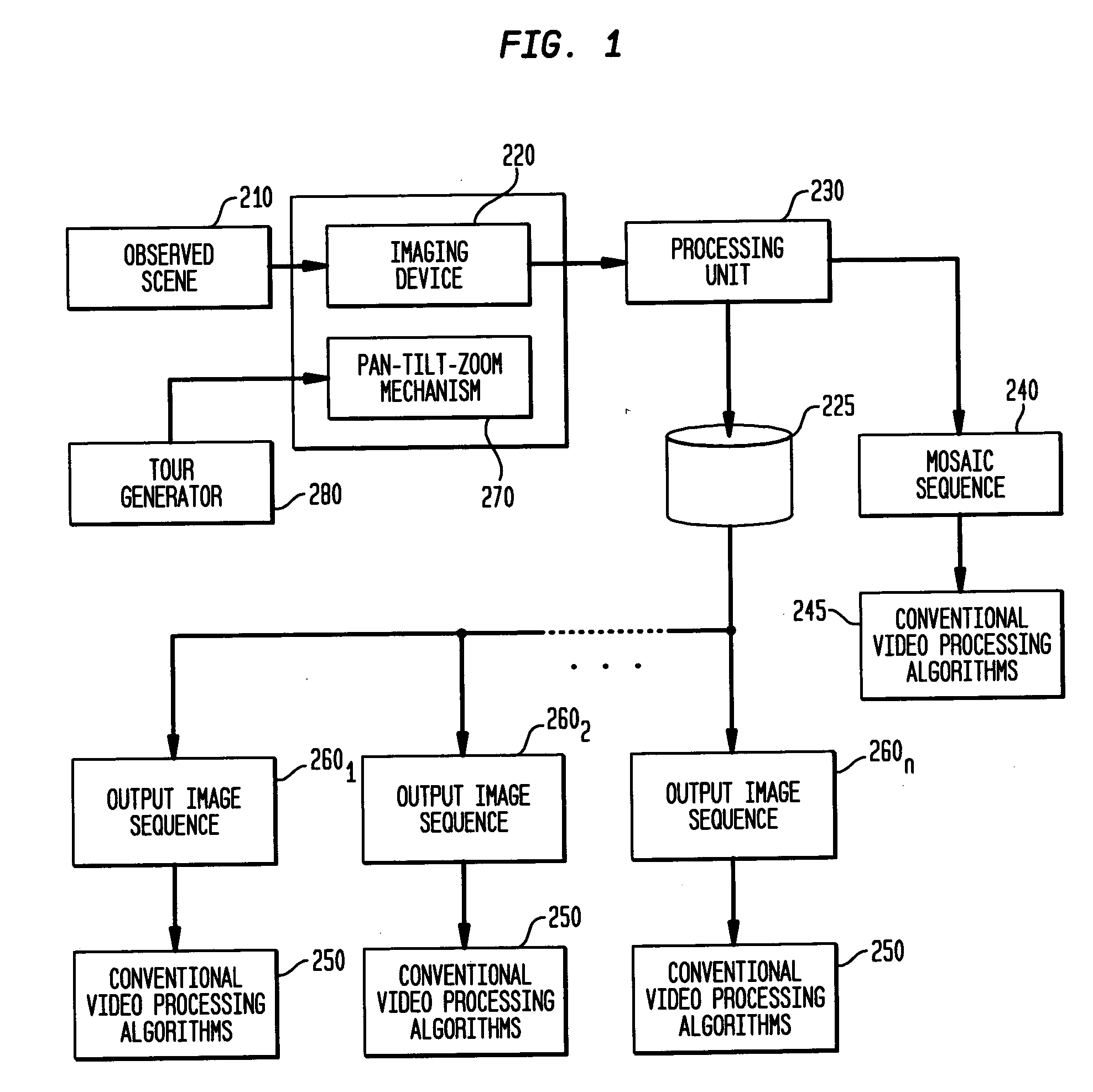
[0022]FIG. 1 depicts the multi-scale visual processing system block diagram 200 for the static camera according to the invention. As shown in FIG. 1, the system generates video of an observed scene 210 by a single imaging device 220. For purposes of the description, it is assumed the imaging device 220 is a moving camera, implemented for taking video images of a field of view according to a programmed tour or, alternatively, manual manipulation, and employing a pan-tilt-zoom, or other motion mechanism, 270. That is, the moving camera may be steered manually or according to a tour (pre-determined or generated “on the fly”) as controlled by a “tour generator” device 280 (FIG. 1) whose parameters (pan, tilt, zoom, rotation, dolly, translate) may or may not be known in advance, or made availa...


PUM


Abstract

A novel system and method of treating the output of moving cameras, in particular ones that enable the application of conventional “static camera” algorithms, e.g., to enable the continuous vigilance of computer surveillance technology to be applied to moving cameras that cover a wide area. According to the invention, a single camera is deployed to cover an area that might require many static cameras and a corresponding number of processing units. A novel system for processing the main video sufficiently enables long-term change detection, particularly the observation that a static object has been moved or has appeared, for instance detecting the parking and departure of vehicles in a parking lot, the arrival of trains in stations, delivery of goods, arrival and dispersal of people, or any other application.

Description

BACKGROUND OF THE INVENTION [0001] 1. Field of the Invention [0002] The present invention generally relates to surveillance systems and methods for providing security, and, more particularly to a novel system and process for analyzing video taken from a non-static, i.e., moving, camera. [0003] 2. Description of the Prior Art [0004] It is expected that for some time to come, camera devices will not be of sufficiently high resolution to acquire sufficient resolution images for some tasks, e.g., surveillance, over wide fields of view. High resolution cameras are expensive, and to cover wide areas they need special lenses that distort the images. The alternative for complete coverage is using many cameras, which is also expensive. Many current surveillance systems cover wide areas with sufficient resolution by deploying pan-tilt-zoom cameras that can be directed to an area of interest within a very large field of view, and zoomed in to give sufficient detail. [0005] Other known systems ...

Claims


Application Information

Patent Timeline
IPC IPC(8): G06K9/00G06K9/32
CPCG06T3/4038G06T7/2033G08B13/19608G08B13/19663H04N7/185G06T7/246
Inventor HAMPAPUR, ARUNPANKANTI, SHARATHCHANDRA U.SENIOR, ANDREW W.
Owner IBM CORP
Learn More